3) 17 bit incremental/absolute encoder, Wt u, C data + m – Yaskawa Sigma II Series Servo System User Manual
Page 356: D data − n
Sigma II User’s Manual
Chapter 8: Ratings and Characteristics
8 - 26
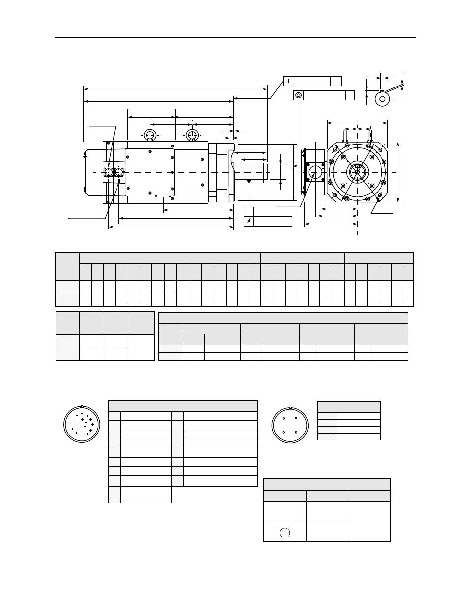
(3) 17 Bit Incremental/Absolute Encoder
Note:
1.
Dimensions are the same when using either incremental or absolute encoders.
2.
Tolerances on the dimensions of flange type LB, of shaft extensions S, and of keyway width and depth are based on JIS (Japanese Industrial Standard)
B0401 “Limits and Fits for Engineering.”
Type
SGMBH-
Motor Body Dimensions
Flange Dimensions
Shaft End Dimension
L
LL
LD
LF
LN
LP KB1 KB2 KG KN
KS
KT CK1 CK2 J
ΦLA ΦLB*
*
LC LE LG
ΦLH ΦLZ ΦS* Q
QK
W***
*
T*** U
3GD A61 32.0
(814)
26.5
(674) 9.29
(236)
9.45
(240)
5.91
(150) 7.87
(200)
20.1
(510)
22.0
(558)
11.6
(295) 8.66
(220)
7.91
(201)
6.85
(174)
2.36
(60)
2.36
(60)
8.66
(220)
11.8
(300)
9.84
(250)
11.8
(300)
0.20
(5)
1.38
(35)
13.8
(350)
0.69
(17.5)
2.76
(70)
5.51
(140)
4.33
(110)
0.79
(20)
0.47
(12)
0.29
(7.5)
4ED A61 33.7
(855)
28.1
(715)
11.1
(281)
7.87
(200)
21.7
(551)
23.6
(599)
13..2
(336)
KT
KS
KN
LC
Q
QK
Φ
S
Φ
LA
Φ
LB
J
LC
4 -
ΦLZ
LE
LG
LN
LF
LP
LD
LL
L
KG
KB1
KB2
0.0020 (0.05)
A
Φ0.0020 (Φ0.05) A
A
0.0012 (0.03)
Fan connector
Encoder connector
Power wiring
W
T
U
Y
Y
Cross-section Y-Y
CK1 CK2
Φ
LH
Φ2.40 (Φ61)
Type
SGMBH-
Approxima
te Mass
lb (kg)
Allowable
Radial Load
lb (N)
Allowable
Thrust Load
lb (N)
3GD A61
507.1
(230)
1674
(7448)
485
(2156)
4ED A61
551.1
(250)
1762
(7840)
Specified Tolerances
Dimension
*
ΦS
**
ΦLB
***T
****W
Unit
Diameter
Tolerance
Diameter
Tolerance
Length
Tolerance
Length
Tolerance
in
2.76
+0.0012 -0.004
9.84
+0.0000 -0.0018 0.47 +0.0000 -0.00433 0.79 +0.0000 -0.00204
mm
70
+0.030 +0.011
250
+0.000 -0.046 12
+0.000 -0.110
20
+0.000 -0.052
A
B
C
D
M
N P
T
E
K
G
F
J
S
R
L
H
Encoder Plug
Fan Connector
Receptacle: CE05-2A18-10PD-B
Non-environmental mating connec-
tor: MS3108B18-10S
(L-Type)
Fan Connector
A
U Phase
B
V Phase
C
W Phase
D
—
A
B
D
C
Power Wiring Terminal Box
Terminal
Connection
Screw Size
U, V, W
Motor
M10
Ground
Connector Wiring on the Encoders
A
—
K
—
B
—
L
—
C Data +
M
—
D Data
−
N
—
E
—
P
—
F
—
R
—
G 0V
S Battery
− (Note*)
H +5V
dc
T
Battery + (Note*)
J
FG (Frame
Ground)
*Note: Used with an absolute
encoder only.