2 list of cn1 terminals, 2 list of cn1 terminals - 18, List of cn1 terminals -18 – Yaskawa Sigma II Series Servo System User Manual
Page 56: Cn1 specifications, The following diagram shows the
Sigma II User’s Manual
Chapter 3: Wiring
3 - 18
3.4.2
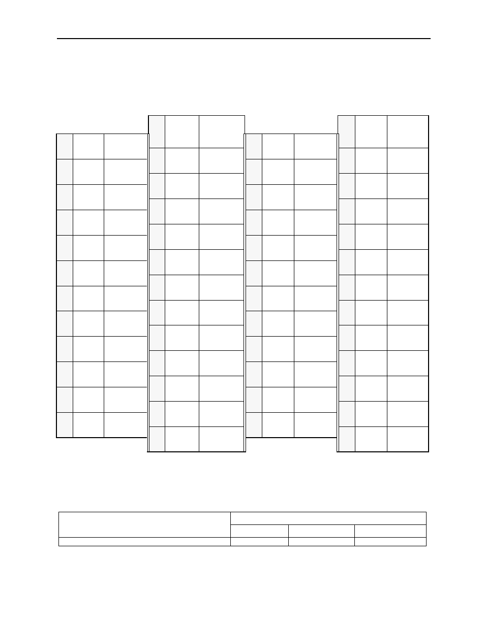
List of CN1 Terminals
The following diagram shows the
layout and specifications of CN1 terminals.
CN1 Terminal Layout
Note 1. Do not use unused terminals for relays.
2. Connect the shield of the I/O signal cable to the connector shell.
Connect the shield to the FG (frame ground) at the servo amplifier-end connector shell only.
CN1 Specifications
1
SG
GND
26
/V-CMP-
(/COIN-)
Speed coin-
cidence
detection
output
2
SG
GND
27
/TGON+
TGON sig-
nal output
3
PL1
Open-collec-
tor reference
power supply
28
/TGON
TGON sig-
nal output
4
SEN
SEN signal
input
29
/S-
RDY+
Servo ready
output
5
V-REF
Reference
speed input
30
/S-RDY
Servo ready
output
6
SG
GND
31
ALM+
Servo alarm
output
7
PULS
Reference
pulse input
32
ALM
Servo alarm
output
8
/PULS
Reference
pulse input
33
PAO
PG divided
output
A-phase
9
T-REF
Torque
reference
input
34
/PAO
PG divided
output
A-phase
10
SG
GND
35
PBO
PG divided
output
B-phase
11
SIGN
Reference
sign input
36
/PBO
PG divided
output
B-phase
12
/SIGN
Reference
symbol input
37
AL01
Alarm code
output
13
PL2
Open-collec-
tor reference
power supply
38
AL02
Alarm code
output
14
/CLR
Clear input
39
AL03
Open-collec-
tor output
15
CLR
Clear input
40
/S-ON
Servo ON
input
16
—
—-
41
P-CON
P operation
input
17
—
—
42
P-OT
Forward
overtravel
input
18
PL3
Open-collec-
tor reference
power supply
43
N-OT
Reverse
overtravel
input
19
PCO
PG divided
output
C-phase
44
/ALM-
RST
Alarm reset
input
20
/PCO
PG divided
output
C-phase
45
/P-CL
Forward cur-
rent limit ON
input
21
BAT (+)
Battery (+)
46
/N-CL
Reverse
current limit
ON input
22
BAT (-)
Battery (-)
47
+24V
-IN
External
input power
supply
23
—
—
48
PSO
S-phase
signal out-
put
24
—
—
49
/PSO
S-phase sig-
nal output
25
/V-CMP+
(/COIN+)
Speed coinci-
dence detec-
tion output
50
—
—
Specifications for Servo Amplifier Connectors
Applicable Receptacles
Solder Type
Case
Manufacturer
10250-52A2JL or Equivalent 50-pin Right Angle Plug 10150-3000VE
10350-52A0-008
Sumitomo 3M Co.