Electronic gear setting examples, Ball screws circular tables belts and pulleys – Yaskawa Sigma II Series Servo System User Manual
Page 117
Sigma II User’s Manual
Chapter 5: Parameter Settings and Functions
5 - 31
Electronic Gear Setting Examples
The following examples show electronic gear settings for different load
mechanisms.
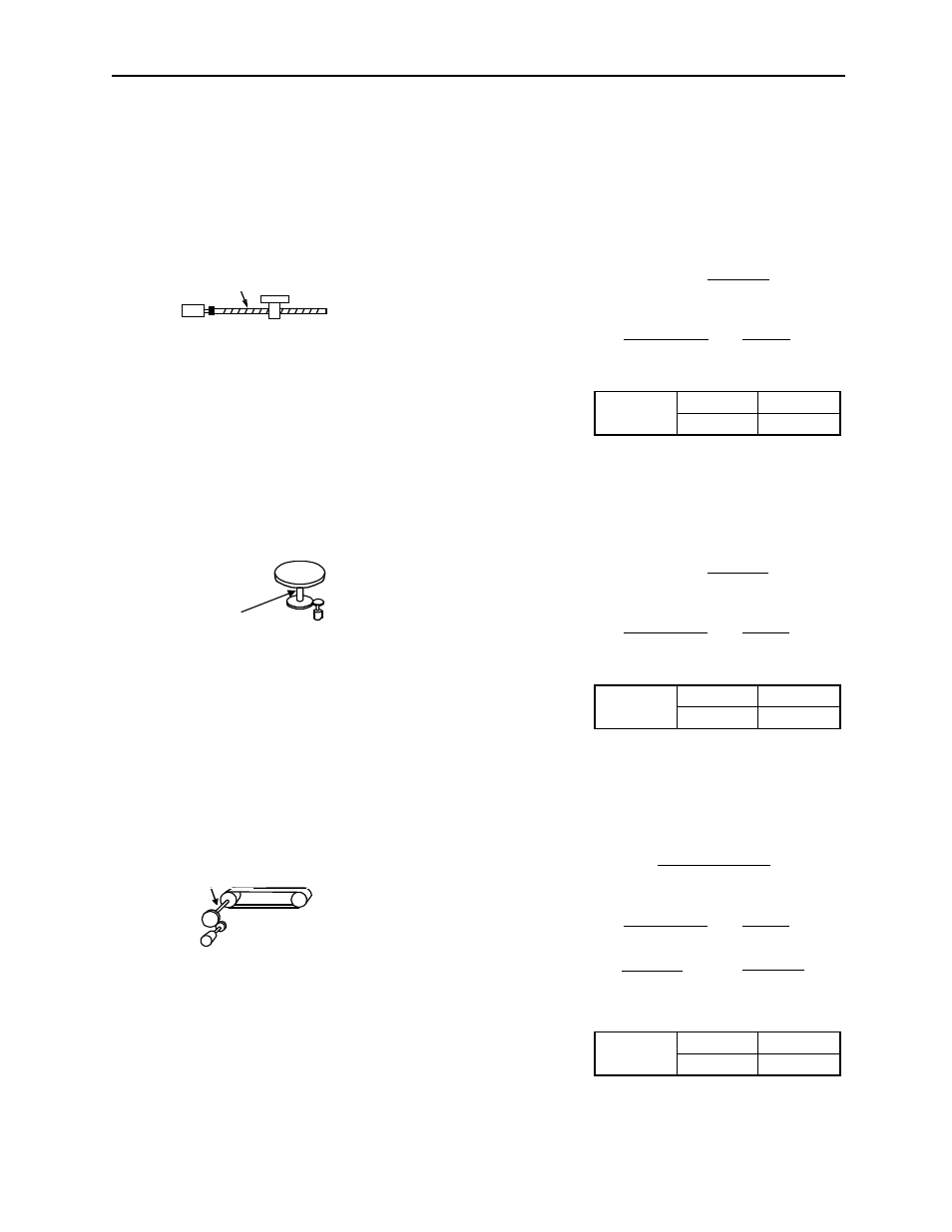
Ball Screws
Circular Tables
Belts and Pulleys
Preset
Values
Pn202
8192
Pn203
6000
Preset
Values
Pn202
24576
Pn203
3600
Preset
Values
Pn202
20480
Pn203
1309
Electronic gear ratio = = =
B
A
---
⎝ ⎠
⎛ ⎞
Pn202
Pn203
Travel distance per load shaft revolution = = 6000
2048
× 4 × 1
6000
0.24in
0.00004in
Load shaft
13-bit incremental
encoder
Ball screw pitch: 0.24in (6mm)
Reference unit 0.00004in (0.0001mm)
Load shaft
13-bit Incremental encoder
Deceleration
ratio: 3:1
Electronic gear ratio = = =
B
A
---
⎝ ⎠
⎛ ⎞
Pn202
Pn203
Travel distance per load shaft revolution = = 3600
2048
× 4 × 3
3600
360°
0.1°
Load Shaft
Reference unit: 0.1°
Electronic gear ratio = = =
B
A
---
⎝ ⎠
⎛ ⎞
Pn202
Pn203
Travel distance per load shaft revolution =
16384
× 4 × 3
12566
3.1416
× 4in
0.0010in
= =
196608
12566
20480
1309
Reference unit: 0.0010in (0.0254mm)
Load shaft
16-bit absolute encoder
Deceleration
ratio: 3:1
Pulley diameter
Φ4in (101.6mm)
= 12566