A.cc, Display and outputs, Status and remedy for alarm – Yaskawa Sigma II Series Servo System User Manual
Page 419
Sigma II User’s Manual
Chapter 9: Inspection, Maintenance, and Troubleshooting
9 - 31
A.CC
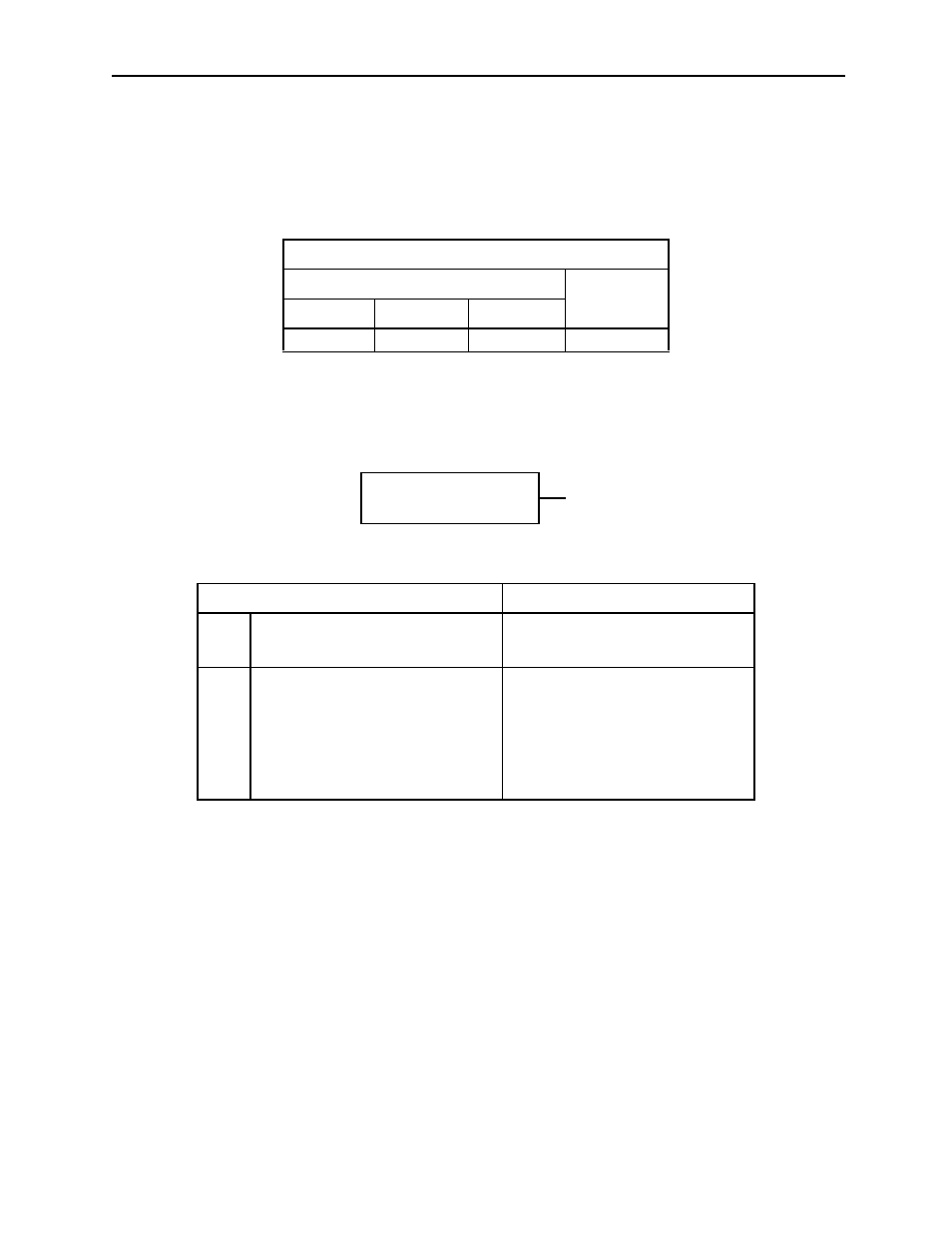
A.CC: Multi-turn Limit Disagreement Alarm
Display and Outputs
Note:
OFF:
Output transistor is OFF (alarm state).
ON:
Output transistor is ON.
Status and Remedy for Alarm
Alarm Outputs
Alarm Code Output
ALM Output
ALO1
ALO2
ALO3
ON
OFF
ON
OFF
Cause of the Problem
Solution
A
Incorrectly set Multi-Turn Limit
Setting parameter (Pn205) in the
servo amplifier.
Change the value in parameter
Pn205.
B
No Multi-Turn Limit value set in
the encoder.
First verify that the Multi-Turn
Limit Setting parameter (Pn205)
is set correctly in the servo ampli-
fier. While in the active alarm
state, change the setting in the
encoder Multi-Turn Limit Setting
parameter (Pn205) using function
Fn013.
At power ON.
A, B