Mating connectors: see page 8-43 – Yaskawa Sigma II Series Servo System User Manual
Page 381
Sigma II User’s Manual
Chapter 8: Ratings and Characteristics
8 - 51
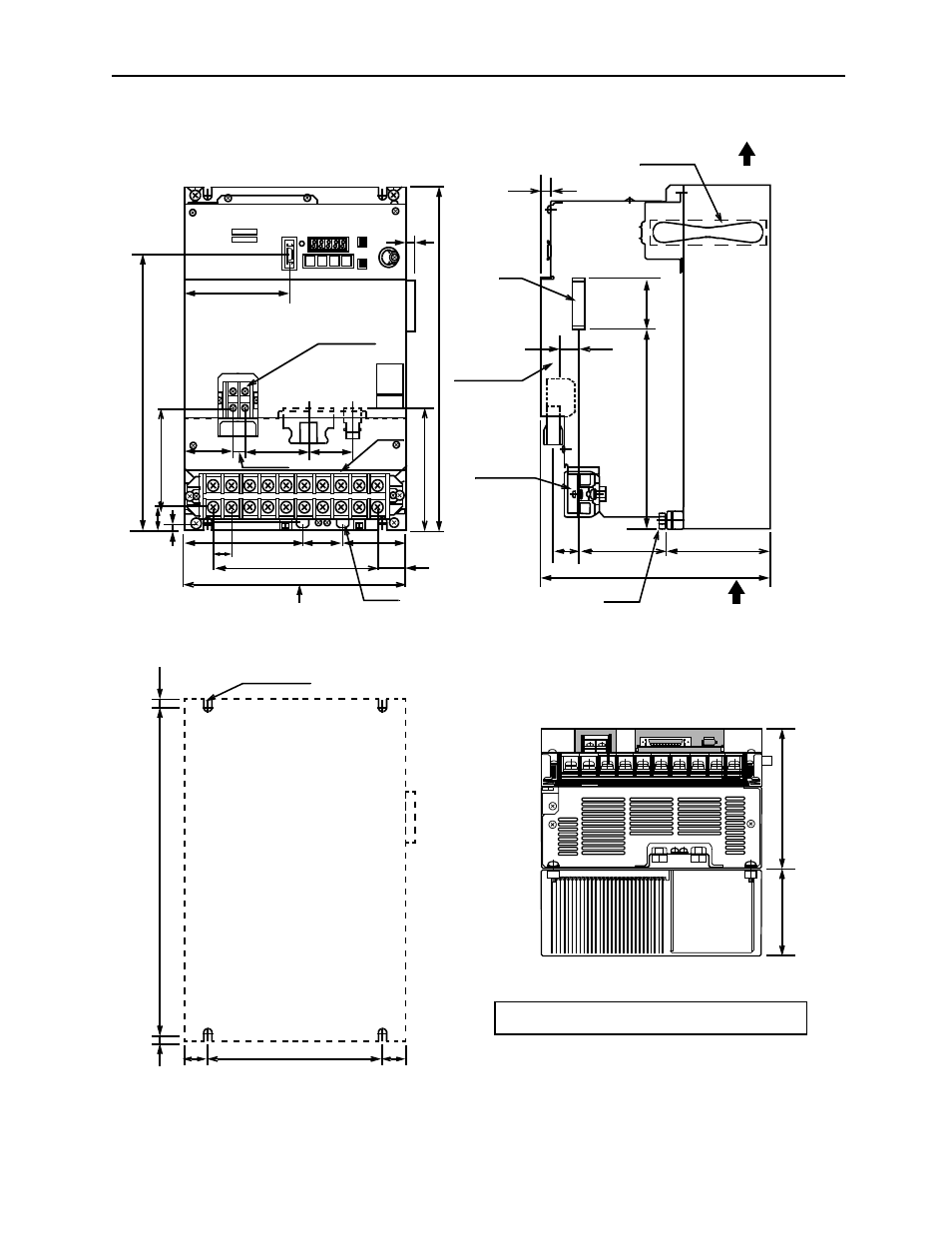
SGDH-60AE, 75AE (Three-phase 200V, 6.0kW, 7.5kW)
L1
L2
L3
B1
+
-
B2
U
V
W
4 x M5 screw holes
Main circuit
0.75 (19)
51
4.86 (123.4)
1.67
(65.6)
2.58
(41)
2.60 (66)
0.49 (12.5)
(2.01)
1.81
(46)
4.33 (110)
Control circuit
terminal M4
CN2
CN3
CN5
CN8
0.31
(8)
CN1
maximum 9.06 (230)
9 x 0.75 (19) = 6.75 (171)
1.11
4.
92 (
125)
ma
xi
m
um 1
3.
78 (
35
0)
0.
98 (25
)
terminal
A
Main circuit
terminal
maximum 9.25 (235)
4.20 (106.8)
3.45 (87.7)
1.06
(27)
10 (0.39)
CN10
Control circuit
terminal
0.83 (21)
1.54 (39)
8.31 (21
1.1)
Ground
terminal
Ground
terminal
3.54 (9
0)
5.
71 (14
5)
0.98
(25)
7.09 (180)
13
.1
9 (3
35
)
0.
30
(7.5)
0.
30
(7.5)
(Mo
unti
ng p
itc
h)
Cooling fan
Air flow
Air flow
Approximate Mass: 31.5lb (14.3kg)
View A
Mounting Hole Diagram
(Mounting pitch)
SERVOPACK 200V
SGDH-
Ver.
11.13
(282
.6)
3.9
6 (
100.5)
0.35 (9)
0.98
(25)
(28.3)
Mating connectors: see page 8-43.