1 interface circuit, 1 interface circuit - 98, Interface circuit -98 – Yaskawa Sigma II Series Servo System User Manual
Page 184: Sen signals
Sigma II User’s Manual
Chapter 5: Parameter Settings and Functions
5-98
5.7.1
Interface Circuit
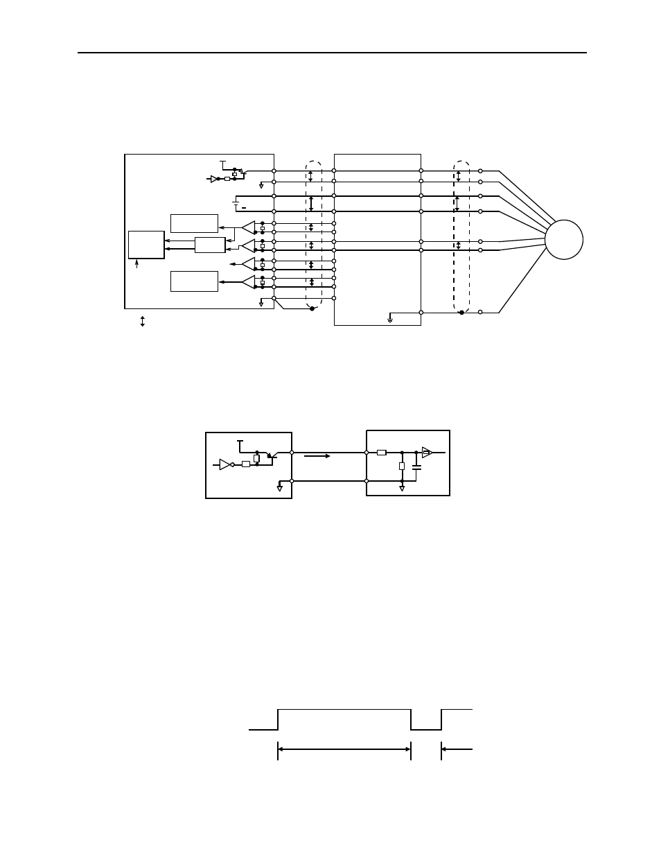
The following diagram shows the standard connections for an absolute encoder
mounted to a servomotor.
Applicable line receivers:SN75175 or MC3486 by TI.
Terminating resistance R:220 to 470
Ω
SEN Signals
•
Wait at least three seconds after turning on the power before raising the SEN
signal to high level.
•
When the SEN signal is changed from low level to high level, the multi-turn data
and initial incremental pulses are transmitted.
•
The motor cannot be operated until these operations are completed, regardless of
the status of the servo ON signal (/S-ON).
Note: If for some reason it is necessary to turn OFF a SEN signal that is already ON, and then to turn it back
ON again, maintain the high level for at least 1.3 seconds before turning it ON and OFF.
SEN
OSEN
BAT
BATO
PAO
/PAO
PBO
/PBO
PCO
/PCO
PSO
/PSO
SG
BAT (+)
BAT (-)
PG5V
PG0V
PS
/PS
Servo amplifier
Host controller
+5V
7406
Battery
0V
CN1
CN2
4
2
21
22
33
34
35
36
19
20
48
49
1
1
2
3
4
5
6
P
P
P
P
P
P
P
P
P
Serial interface
circuit
Edge
Line receiver
R
R
R
R
PA
PB
PC
PS
detection
Up/down
counter
UP
DOWN
Clear
H (1)
G (2)
T (3)
S (4)
C (5)
D (6)
J
Shielded wire (shell)
P: Indicates twisted pair wires
Connector shell
+
0V
Serial interface
circuit
PG
SEN
OSEN
Host controller
Servo amplifier
CN1-2
CN1-4
+5V
Approx. 1mA
at high level
0V
7406 or
equivalent
0V
1000
Ω
4.7k
Ω
1
μF
OFF
ON = high level
1.3s minimum
OFF
ON
15ms (minimum)
SEN signal