Yaskawa Sigma II Series Servo System User Manual
Page 437
Sigma II User’s Manual
Appendix A: Host Controller Connection Examples
A - 5
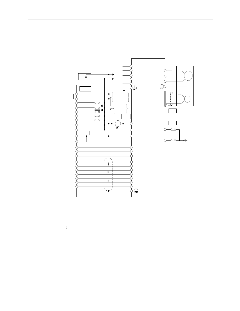
A.4 Connecting OMRON's C500-NC221 Position Control Unit
The following diagram shows an example of connecting to an OMRON C500-NC221
Position Control Unit. In this example, the servo amplifier is used in Speed Control
Mode.
*1. The ALM signal is output for approximately two seconds when the power is turned
ON. Take this into consideration when designing the power ON sequence. The ALM
signal actuates the alarm detection relay 1Ry to stop main circuit power supply to the
servopack.
*2. Connect the shield wire to the connector shell.
*. P indicates twisted pair wires.
Note Only signals applicable to OMRON’s C500NC221 Position Control Unit and
Yaskawa’s SGDM servo amplifier are shown here.
P
P
P
CN2
19
36
35
20
1
34
33
CCWLX
STPX
ORGX
EMGX
DC GND
DC GND
CWLX
XAG
XOUT
OUT1X
+24V
0V
XB
XC
XA
+24V +
-
I/O Power Supply
EXT IN
X axis (Y axis)
+24V
3Ry
4Ry
M/D
CN1
ALM+
ALM-
VREF (TREF)
SG
POT
NOT
3Ry
4RY
3 (13)
4 (14)
5 (15)
6 (16)
1
11
2 (12)
9
8
6 (22)
1 (17)
15 (13)
16 (14)
4 (20)
5 (21)
7 (23)
8 (24)
9 (25)
3 (19)
5 (9)
6 (10)
31
32
47
40
43
42
C500NC221
(Made by OMRON)
*1
ON when
positioning is
canceled.
ON when
proximity is
detected.
1Ry
L1C
L3
L2
L1
L2C
SON
+24VIN
*2 Connec
tor shell
CN1
Servomotor
*3
11
12
XB
XC
XA
024 V
+24 V
PAO
SG
PCO
PBO
*PAO
*PCO
*PBO
024 V
M
PG
Servopack
W
V
A (1)
B (2)
C (3)
D (4)
U
SGDM