Yaskawa G7 Drive User Manual
Page 102
Trial Operation Procedures
4-
13
* 1. Not normally displayed. Displayed only when a motor switch command is set for a multi-function digital input (one of H1-01 to H1-05 set to 16).
* 2. The factory setting depends on the Drive capacity. Values are given for a 200-240 V class, 0.4 kW Drive.
* 3. The setting range is 10% to 200% of the Drive capacity.
* 4. For V/f control, the only setting that is possible is 2 (stationary autotuning for line-to-line resistance only).
* 5. For fixed output motors, set the base speed value.
* 6. For drive motors or for specialized vector motors, the voltage or frequency may be lower than for general-purpose motors. Always confirm the informa-
tion on the nameplate or in test reports. If the no-load values are known, input the no-load voltage in T1-03 and the no-load current in T1-05 to ensure
accuracy.
* 7. The settings that will ensure stable vector control are between 50% and 100% of the Drive rating.
Refer to page 3-15 for Digital Operator displays during autotuning.
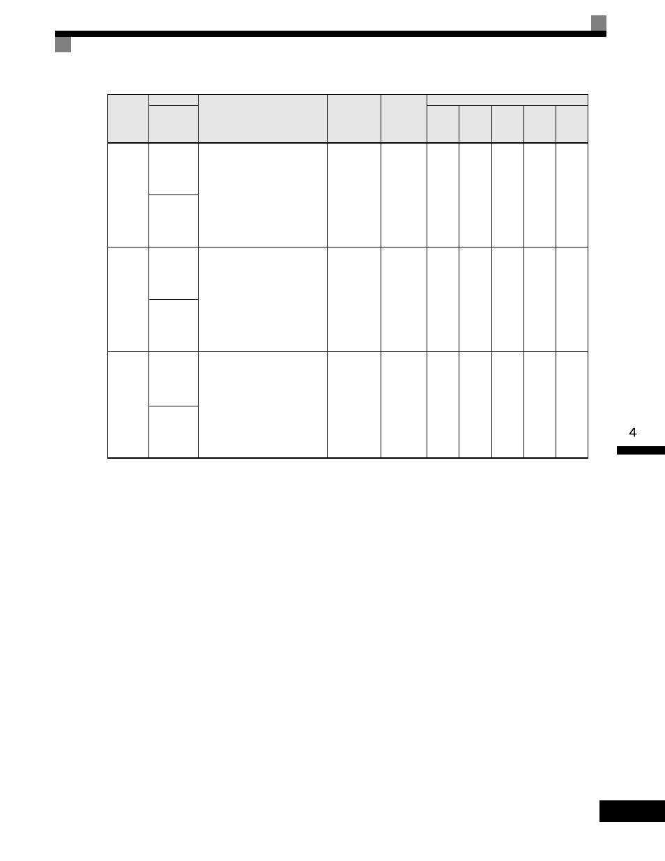
T1-06
Number of
motor
poles
Set the number of motor poles.
2 to 48
poles
4 poles
-
-
Yes
Yes
Yes
Number of
Poles
T1-07
Motor
base speed
Set the base speed of the motor
in min
−1
.
*3 *5
0 to 24000
1750
min
−1
-
-
Yes
Yes
Yes
Rated
Speed
T1-08
Number of
PG pulses
when turn-
ing
Set the number of pulses for
the PG (pulse generator or
encoder). Set the number of
pulses per motor revolution
without a multiplication factor.
0 to 60000
600
-
Yes
-
Yes
-
PG Pulses/
Rev
Table 4.3 Parameter Settings before Autotuning(Continued)
Parameter
Number
Name
Display
Setting
Range
Factory
Setting
Data Displays during Autotuning
V/f
V/f with
PG
Open-
loop
Vector
1
Flux
Vector
Open-
loop
Vector
2
Display