Shunt connector cn15 and dip switch s1 – Yaskawa G7 Drive User Manual
Page 57
2
-26
* 1. For a 3-wire sequence, the default settings are a 3-wire sequence for S5, multi-step speed setting 1 for S6 and multi-step speed setting 2 for S7.
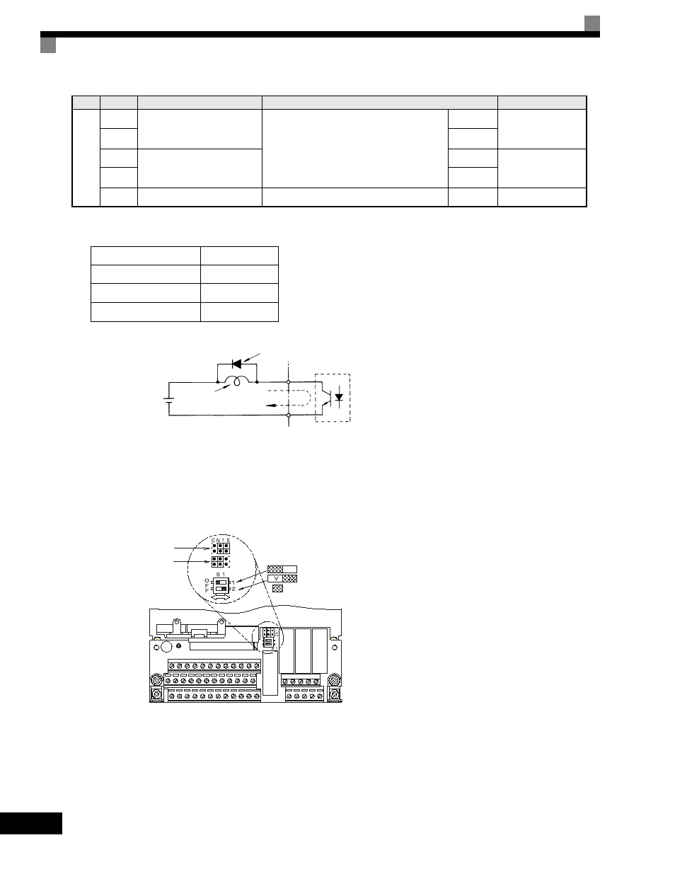
* 2. When driving a reactive load, such as a relay coil, always insert a flywheel diode as shown in Fig 2.14.
* 3. Pulse input specifications are given in the following table.
Fig 2.14 Flywheel Diode Connection
Shunt Connector CN15 and DIP Switch S1
The shunt connector CN15 and DIP switch S1 are described in this section.
Fig 2.15 Shunt Connector CN15 and DIP Switch S1
RS-
485/
422
R+
MODBUS
communications input
For 2-wire RS-485, short R+ and S+ as well
as R- and S-.
Differential input,
PHC isolation
R-
S+
MODBUS
communications output
Differential output,
PHC isolation
S-
IG
Communications shield wire
-
-
Low level voltage
0.0 to 0.8 V
High level voltage
3.5 to 13.2 V
H duty
30% to 70%
Pulse frequency
0 to 32 kHz
Table 2.10 Control Circuit Terminals (Continued)
Type
No.
Signal Name
Function
Signal Level
External power:
48 V max.
Coil
Flywheel diode
50 mA max.
The rating of the flywheel diode
must be at least as high as the
circuit voltage.
ON
OFF
Terminating resistance*
Analog input switch
Factory settings
Analog output switch
Voltage output
Current output
*Note: Refer to Table 2.11 for S1 functions and
to Table 2.13 for Sinking/Sourcing Mode
and Input Signals.