Application precautions – Yaskawa G7 Drive User Manual
Page 378
Options
6-
161
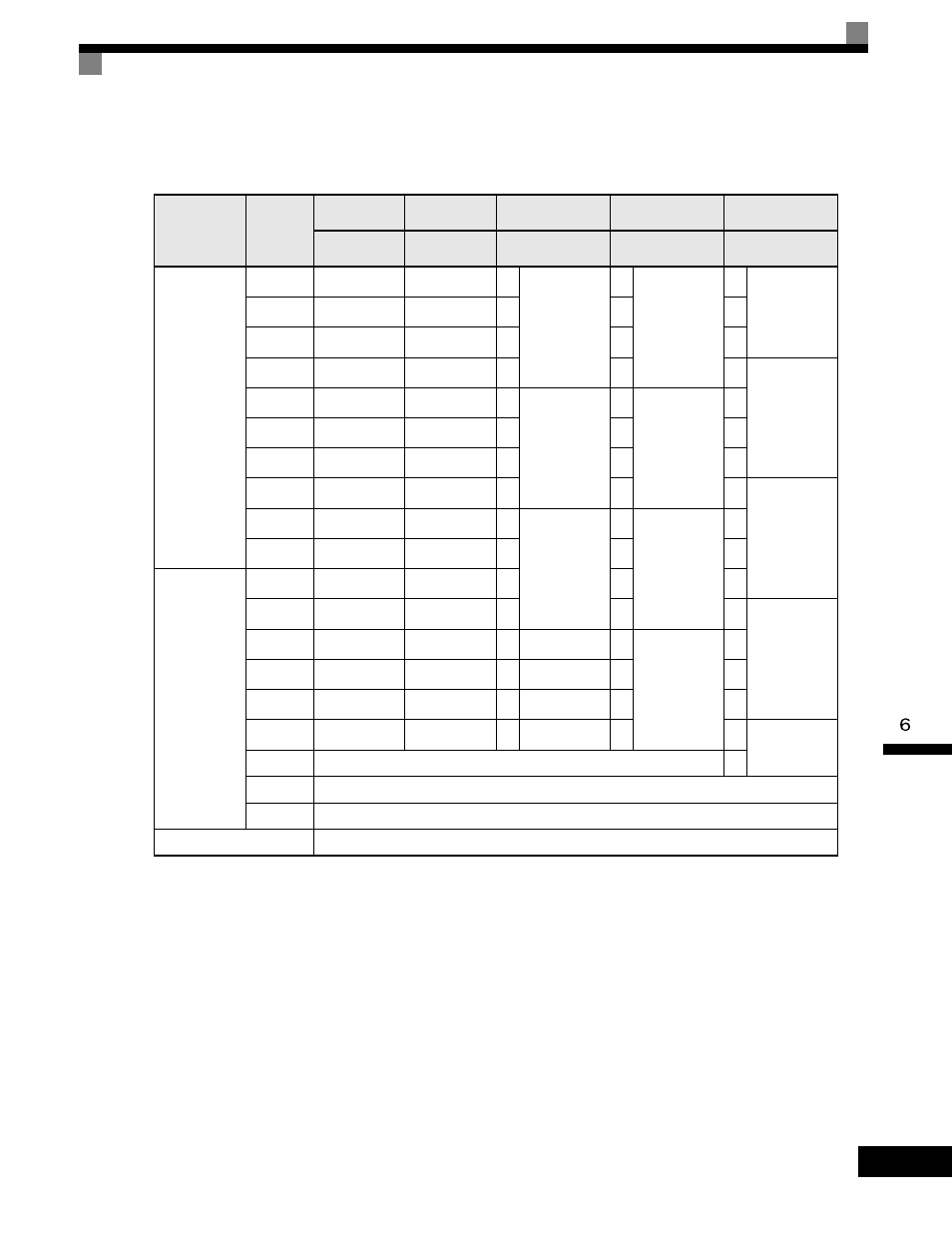
Selecting Input Terminal Functions for the DI-16H2 Digital Reference Card
The frequency reference from the DI-16H2 Card is determined by the setting of F3-01 and the 12/16-bit
switch on the Option card. The possible settings are listed in the following table.
Application Precautions
•
The maximum frequency (100% speed) reference will be used when the binary input is set (setting: 6 or 7)
and all bits are 1.
•
Setting F3-01 to 6 is valid only when the D1-16H2 is used. Using this setting, a frequency from 0.00 to
399.8Hz can be set in BCD. The sign bit is used as a data bit, so only positive (plus) data can be set. Also,
the digit starts from 0, so the minimum setting is 0.02Hz.
Selecting the Input Terminal Function for a DI-08 Digital Reference Card
The frequency reference from a DI-08 Card is determined by the setting of F3-01, as shown in the following
table.
Terminal
Pin No.
12-bit Binary
with Sign
16-bit Binary
with Sign
3-digit BCD
with Sign
4-digit BCD
with Sign
4-digit BCD
without Sign
F3-01 = 7
S1: 12 bit
F3-01 = 7
S1: 16 bit
F3-01 = 0 to 5
S1: 12 bit
F3-01 = 0 to 5
S1: 16 bit
F3-01 = 6
S1: 16 bit
TC1
1
Bit 1 (2
0
)
Bit 1 (2
0
)
1
BDC digit 1
(0 to 9)
1
BDC digit 1
(0 to 9)
2
BDC digit 1
(2 to 9)
2
Bit 1 (2
1
)
Bit 1 (2
1
)
2
2
4
3
Bit 1 (2
2
)
Bit 1 (2
2
)
4
4
8
4
Bit 1 (2
3
)
Bit 1 (2
3
)
8
8
1
BDC digit 2
(0 to 9)
5
Bit 1 (2
4
)
Bit 1 (2
4
)
1
BDC digit 2
(0 to 9)
1
BDC digit 2
(0 to 9)
2
6
Bit 1 (2
5
)
Bit 1 (2
5
)
2
2
4
7
Bit 1 (2
6
)
Bit 1 (2
6
)
4
4
8
8
Bit 1 (2
7
)
Bit 1 (2
7
)
8
8
1
BDC digit 3
(0 to 9)
9
Bit 1 (2
8
)
Bit 1 (2
8
)
1
BDC digit 3
(0 to 9)
1
BDC digit 3
(0 to 9)
2
10
Bit 1 (2
9
)
Bit 1 (2
9
)
2
2
4
TC2
1
Bit 1 (2
10
)
Bit 1 (2
10
)
4
4
8
2
Bit 1 (2
11
)
Bit 1 (2
11
)
8
8
1
BDC digit 4
(0 to 9)
3
-
Bit 1 (2
12
)
-
1
BDC digit 4
(0 to 9)
2
4
-
Bit 1 (2
13
)
-
2
4
5
-
Bit 1 (2
14
)
-
4
8
6
-
Bit 1 (2
15
)
-
8
1
BDC digit 5
(0 to 3)
7
Sign signal (0: Forward, 1: Reverse)
2
8
SET (read) signal (1: Read)
9
Input signal common (0 V)
TC3
Shield wire connection terminal