Dc braking stop, Coast to stop with timer, Info – Yaskawa G7 Drive User Manual
Page 229: Fig 6.14 dc injection braking (db) stop, Fig 6.15 coast to stop with timer
6
-12
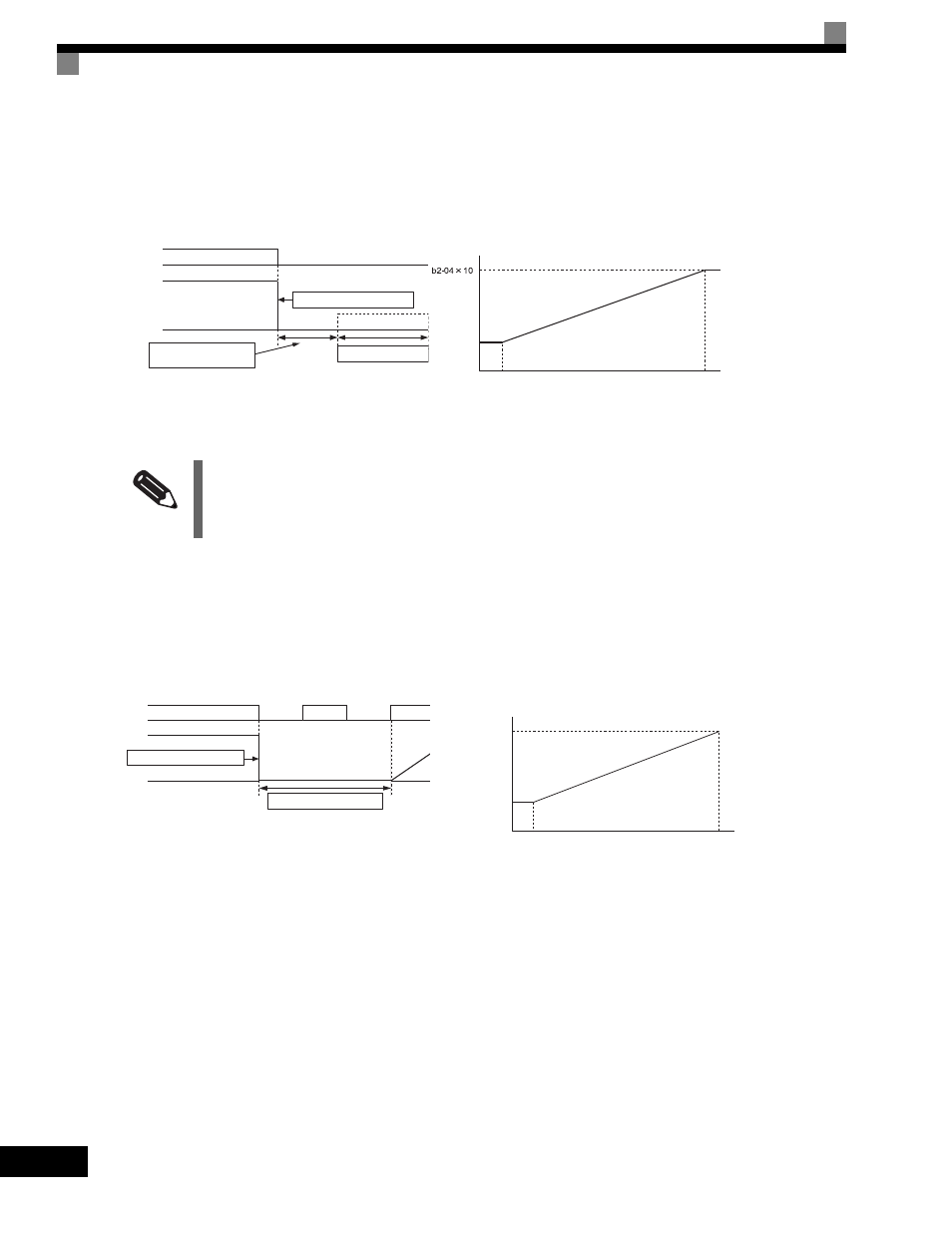
DC Braking Stop
If the stop command is input (i.e., the run command is turned OFF) when b1-03 is set to 2, a wait is made for
the time set in L2-03 (Minimum Baseblock (BB) Time) and then the DC injection brake current set in b2-02 is
sent to the motor to apply a DC injection brake to stop the motor. The DC injection brake time is determined
by the set value in b2-04 and the output frequency when the stop command is input.
Fig 6.14 DC Injection Braking (DB) Stop
Coast to Stop with Timer
If the stop command is input (i.e., the run command is turned OFF) when b1-03 is set to 3, the Drive output is
interrupted to coast the motor to a stop. After the stop command is input, run commands are ignored until the
time T has elapsed. The time T depends upon the output frequency when the stop command is input and the
deceleration time.
Fig 6.15 Coast to Stop with Timer
INFO
Lengthen the Minimum Baseblock Time (L2-03) when an overcurrent (OC) occurs during stopping.
Inverter output voltage interrupted
Output frequency
Run command
ON
OFF
Minimum baseblock
time (L2-03)
DC injection brake time
DC injection brake
10%
100% (maximum output frequency)
Output frequency at
stop command input
DC injection brake time
b2-04
Output
frequency
Run command
ON
ON
ON
OFF
OFF
Inverter output voltage interrupted
Operation wait time T
100% (Maximum output frequency)
Minimum output frequency
Output frequency at
stop command input
Operation wait time T
Deceleration time
(e.g., C1-02)
Minimum baseblock
time (L2-03)