Drive mode indicators, Fig 3.7 operation in autotuning mode – Yaskawa G7 Drive User Manual
Page 88
Drive Mode Indicators
3-
15
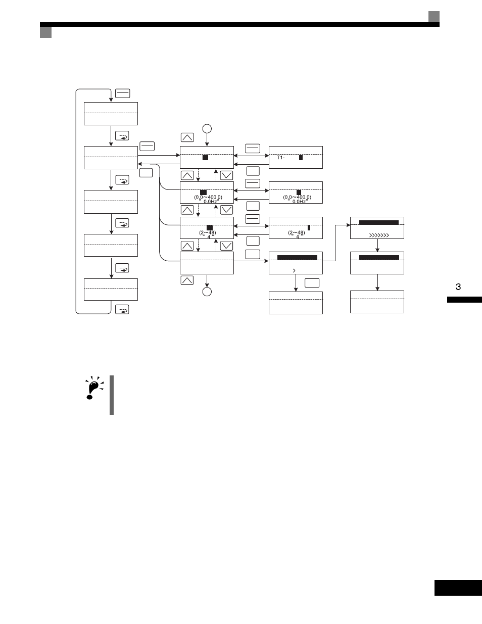
* TUn10 will be displayed during rotational autotuning and TUn11 will be displayed during stationary autotuning. The DRIVE indicator will light when
autotuning starts.
Fig 3.7 Operation in Autotuning Mode
IMPORTANT
The setting displays in for autotuning depend on the control mode (V/f, V/f with PG, open-loop vector 1, open-
loop vector 2, or flux vector). If a fault occurs during autotuning, refer to Chapter 7 Troubleshooting.
START GOAL
** Main Menu **
-DRIVE-
Operation
** Main Menu **
-QUICK-
Quick Setting
** Main Menu **
-ADV-
Programming
** Main Menu **
-VERIFY-
Modified Consts
** Main Menu **
-A.TUNE-
Auto-Tuning
MENU
MENU
MENU
MENU
MENU
Monitor Display
Setting Display
Mode Selection Display
DATA
ENTER
Tuning Mode Sel
-A.TUNE-
T1-
01
=0 *0*
ESC
DATA
ENTER
A
DATA
ENTER
ESC
DATA
ENTER
ESC
RUN
Auto-Tuning
-A.TUNE-
Press RUN key
Tuning Ready ?
Tune Proceeding
-A.TUNE-
48.0Hz/10.5A
DATA
ENTER
ESC
Standard Tuning
Tuning Mode Sel
-A.TUNE-
01 =
0
*0*
Rated Frequency
-A.TUNE-
T1-
05
= 60.0Hz
Number of Poles
-A.TUNE-
T1-
06
= 4
Rated Frequency
-A.TUNE-
T1-
05
=
0
60.0Hz
Number of Poles
-A.TUNE-
T1- 06 =
04
A
Rdy
Tune Aborted
-A.TUNE-
STOP key
STOP
The display will
automatically
change depending
on the status of
autotuning.
Standard Tuning
START GOAL
Tune Proceeding
-A.TUNE-
48.0Hz/10.5A
Tune Successful
-A.TUNE-
Tune Successful
Tune Proceeding
-A.TUNE-
"0"
"0"
0.0Hz/0.0A