Coast to stop, Info – Yaskawa G7 Drive User Manual
Page 228
Stopping Methods
6-
11
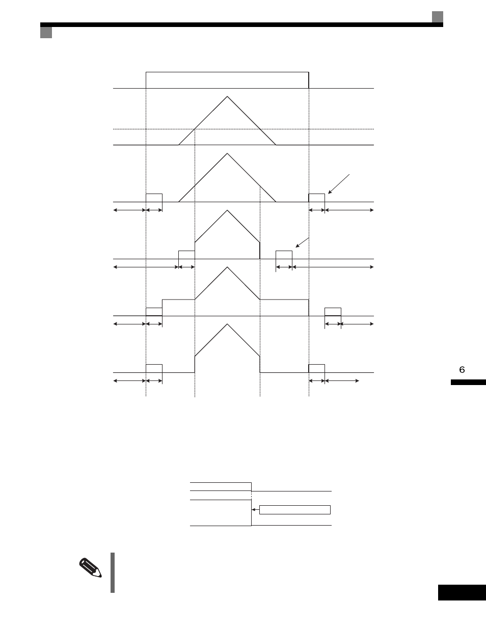
The operation after stopping depends on the setting of b1-05 when flux vector control is selected (A1-02 = 3).
Fig 6.12 Deceleration to Stop (for Flux Vector Control)
Coast to Stop
If the stop command is input (i.e., the run command is turned OFF) when b1-03 is set to 1, the Drive output
voltage is interrupted. The motor coasts to a stop at the deceleration rate that counterbalances damage to the
machine and inertia including the load.
Fig 6.13 Coast to Stop
INFO
After the stop command is input, run commands are ignored until the Minimum Baseblock Time (L2-03) has
elapsed.
Injection brake
time at start
b2-03
Zero speed
control
b2-04
Baseblock
b2-03
b2-04
b2-03
b2-04
b2-03
b2-04
Run command OFF
ON
OFF
Frequency reference
via analog input
0
E1-09
b1-05=0
(frequency reference)
Run command turns OFF
and zero speed control start
when motor speed drops to b2-01.
b1-05=1
(Coast)
b1-05=2
(Run on E1-09)
b1-05=3
(Zero speed)
Injection brake
time at start
Injection brake
time at start
Injection brake
time at start
Baseblock
Baseblock
Baseblock
Baseblock
Baseblock
Baseblock
Baseblock
Zero speed
control
Zero speed control
Zero speed control
Frequency reference drops to less
than E1-09 and zero speed control
starts when motor speed drops to
b2-01.
Run command turns OFF
and zero speed control start
when motor speed drops to b2-01.
Run command turns OFF
and zero speed control start
when motor speed drops to b2-01.
Output frequency
Run command
ON
OFF
Inverter output freqeuencty interrupted.