Related parameters – Yaskawa G7 Drive User Manual
Page 244
Adjusting Frequency References
6-
27
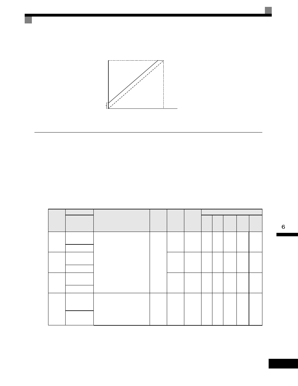
For example, if H3-02 is 100%, H3-03 is 0%, and terminal A2 is set to 1 V, the frequency reference from
terminal A1 when 0Vis input to A1 will be 10%.
Operation Avoiding Resonance (Jump Frequency Function)
The jump frequency function operates the motor while avoiding resonance caused by characteristic frequen-
cies in the machinery.
This function is effective in creating a frequency reference dead band.
During constant-speed operation, operation within the jump frequency range is prohibited. Smooth operation
still used during acceleration and deceleration, i.e., jumps are not performed.
Related Parameters
The relationship between the output frequency and the jump frequency reference is as follows:
Parameter
Number
Name
Description
Setting
Range
Factory
Setting
Change
during
Operation
Control Methods
Display
V/f
V/f
with
PG
Open
Loop
Vector
1
Flux
Vector
Open
Loop
Vector
2
d3-01
Jump
Frequency 1
This parameter allows
programming of up to three
prohibited frequency reference
points for eliminating problems
with resonant vibration of the
motor / machine. This feature
does not actually eliminate the
selected frequency values, but
will accelerate and decelerate the
motor through the prohibited
bandwidth.
0.0
to
400.0
0.0Hz
No
A
A
A
A
A
Jump Freq 1
d3-02
Jump
Frequency 2
0.0Hz
No
A
A
A
A
A
Jump Freq 2
d3-03
Jump
Frequency 3
0.0Hz
No
A
A
A
A
A
Jump Freq 3
d3-04
Jump
Frequency
Width
This parameter determines the
width of the deadband around
each selected prohibited
frequency reference point. A
setting of "1.0" will result in a
deadband of +/- 1.0Hz..
0.0
to
20.0
1.0Hz
No
A
A
A
A
A
Jump
Bandwidth
Terminal A1 input voltage
Frequency reference
H3-02
10%
Bias
0 V
10 V