Motor 2 v/f pattern: e3 – Yaskawa G7 Drive User Manual
Page 148
User Parameter Tables
5-
37
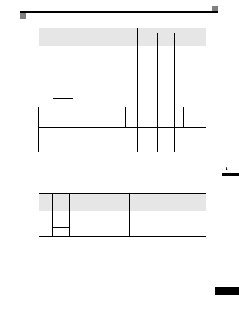
User parameters for motor 1 are shown in the following table.
* 1. The factory setting depends upon the Drive capacity. The value for a 200-240V class Drive of 0.4 kW is given.
* 2. The setting range is 10% to 200% of the Drive's rated output current. The value for a 200-240V class Drive of 0.4 kW is given.
* 3. The factory setting depends upon the Drive capacity. The value for a 200-240V class Drive of 0.4 kW is given.
Motor 2 V/f Pattern: E3
User parameters for motor 2 V/f characteristics are shown in the following table.
E2-09
Motor
Mechanical
Loss
Sets the motor mechanical
loss as a percentage of motor
rated power (kW) capacity.
Adjust in the following
circumstances:
-when torque loss is large due
to motor bearing friction.
-when the torque loss in the
load is large.
0.0
to
10.0
0.0%
No
No
No
A
A
A
316H
Mechanical
Loss
E2-10
Motor Iron
Loss for
Torque
Compensation
Sets the motor iron loss in
watts (W).
0
to
65535
14 W
*1
No
A
A
No
No
No
317H
Tcomp Iron
Loss
E2-11
Motor Rated
Output
Sets the motor rated power in
kilowatts (kW). This value is
automatically set during
Auto-Tuning.
1HP = 0.746kW
0.00 to
650.00
0.40
kW
*1
No
Q
Q
Q
Q
Q
318H
Mtr Rated
Power
E2-12
Motor
Iron-core
Saturation
Coefficient 3
Sets the motor iron saturation
coefficient at 130% of
magnetic flux.
This value is automatically
set during rotational
Auto-Tuning.
1.30
to
5.00
1.30
No
No
No
A
A
A
328H
Saturation
Comp3
Parameter
Number
Name
Description
Setting
Range
Factory
Setting
Change
during
Operation
Control Methods
MODBUS
Register
Display
V/f
V/f
with
PG
Open
Loop
Vector
1
Flux
Vector
Open
Loop
Vector
2
E3-01
Motor 2
Control
Method
Selection
0: V/f control
1: V/f control with PG
2: Open-loop vector control
3: Flux vector control
4: Open-loop vector control 2
0 to 4
2
No
A
A
A
A
A
319H
Control
Method
Parameter
Number
Name
Description
Setting
Range
Factory
Setting
Change
during
Operation
Control Methods
MODBUS
Register
Display
V/f
V/f
with
PG
Open
Loop
Vector
1
Flux
Vector
Open
Loop
Vector
2