Modbus message example, Reading storage register contents – Yaskawa G7 Drive User Manual
Page 306
Individual Functions
6-
89
Error Check
Errors are detected during communications using CRC-16. Perform calculations using the following method.
1. The factory setting for CRC-16 communications is usually 0, but when using the MODBUS system, set the
factory setting to 1 (i.e., set all 16 bits to 1).
2. Calculate CRC-16 using MSB as slave address LSB, and LSB as the MSB of the final data.
3. Also calculate CRC-16 for response messages from the slaves, and compare them to the CRC-16 in the
response messages.
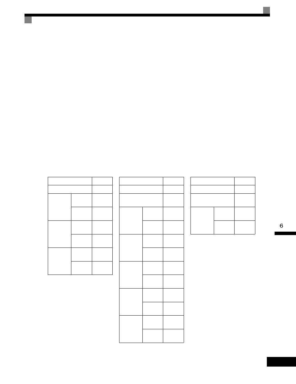
MODBUS Message Example
An example of MODBUS command/response messages is given below.
Reading Storage Register Contents
Read the contents of the storage register only for specified quantities whose addresses are consecutive, starting
from a specified address. The contents of the storage register are separated into higher place 8 bits and lower
place 8 bits, and comprise the data within response messages in address order.
The following table shows message examples when reading status signals, error details, data link status, and
frequency references from the slave 2 Drive.
Command Message
Response Message
(During Normal Operation)
Response Message
(During Error)
Slave Address
02H
Slave Address
02H
Slave Address
02H
Function Code
03H
Function Code
03H
Function Code
83H
Start
Address
Higher
place
00H
Data quantity
08H
Error code
03H
Lower
place
20H
Lead stor-
age register
Higher
place
00H
CRC-16
Higher
place
F1H
Quantity
Higher
place
00H
Lower
place
65H
Lower
place
31H
Lower
place
04H
Next stor-
age register
Higher
place
00H
CRC-16
Higher
place
45H
Lower
place
00H
Lower
place
F0H
Next stor-
age register
Higher
place
00H
Lower
place
00H
Next stor-
age register
Higher
place
01H
Lower
place
F4H
CRC-16
Higher
place
AFH
Lower
place
82H