Selecting analog monitor items, Adjusting the meter, Switching analog monitor signal levels – Yaskawa G7 Drive User Manual
Page 298
Monitor Parameters
6-
81
Selecting Analog Monitor Items
The digital operator monitor items (U1-
[status monitor]) are output from multi-function analog output
terminals FM-AC and AM-AC. Refer to Chapter 5 User Parameters, and set the values for the
part of
U1-
(status monitor).
Alternatively, you can output monitor items (U1-
[status monitor]) from analog output option terminal
channels 1 and 2 on analog monitor cards AO-08 and AO-12. Refer to the table of parameters, and set the val-
ues.
Adjusting the Analog Monitor Items
Adjust the output voltage for multi-function analog output terminals FM-AC and AM-AC using the gain and
bias in H4-02, H4-03, H4-05, and H4-06. Also, adjust the output voltage for output channels 1 and 2 of Ana-
log Output Option Cards AO-08 and AO-12 using the gain and bias in F4-02, F4-04, and F4-06.
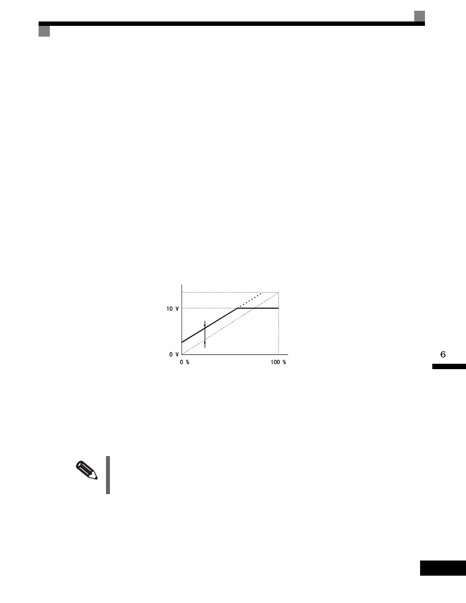
Adjusting the Meter
Display the data setting display for the gain and bias parameters corresponding to the output channel of the
Drive Unit and the AO Option Card while the Drive is stopped to output the following voltages to the analog
monitor terminal, to enable meter adjusting while the Drive is stopped.
10 V/100% monitor output
× output gain + output bias
Fig 6.53 Monitor Output Adjustment
Switching Analog Monitor Signal Levels
Monitor items corresponding to 0 to ±10Voutput 0 to 10Vsignals when the monitor value is positive (+), and 0
to -10Vsignals when the monitor value is negative (-). For monitor items corresponding to 0 to ±10 V, refer to
Chapter 5 User Parameters.
INFO
You can select the signal levels separately for multi-function analog output terminals and analog output option
terminals.
Output voltage
Gain x 10 V
Bias x 10/100 V
Monitor item