Related parameters – Yaskawa G7 Drive User Manual
Page 377
6
-160
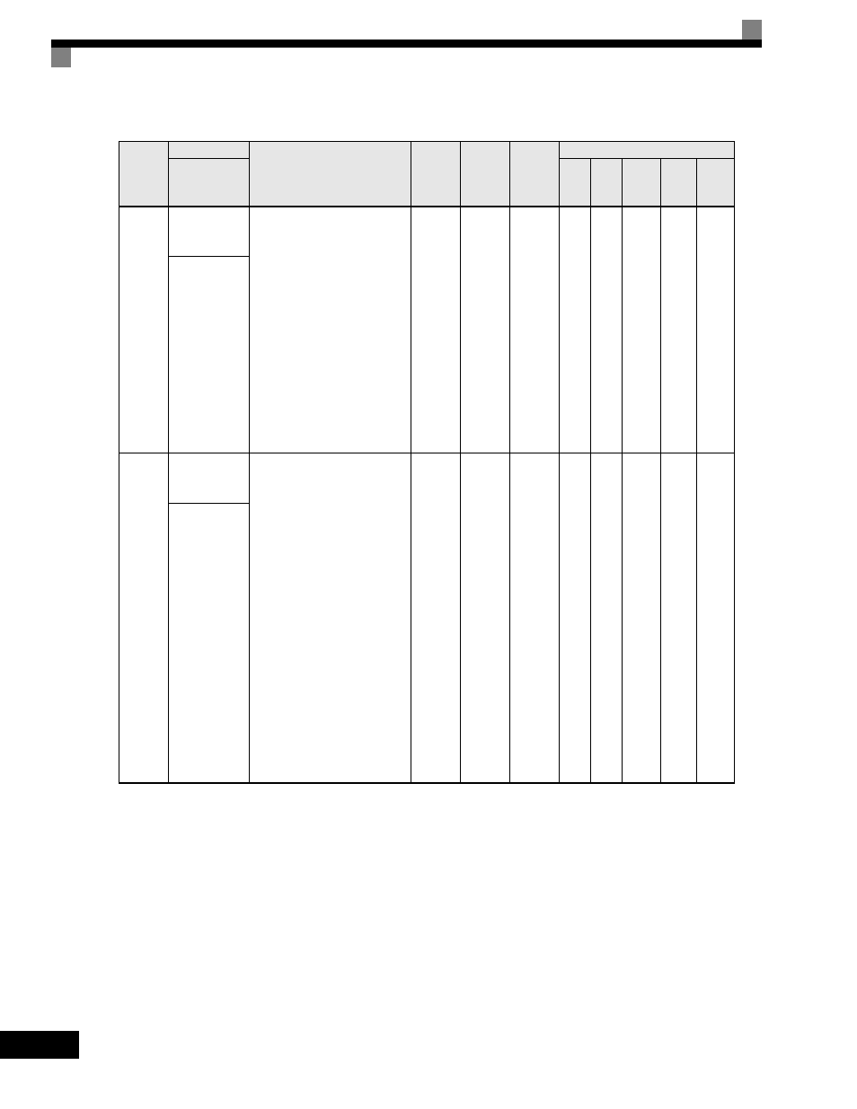
Related Parameters
Parameter
Number
Name
Description
Setting
Range
Factory
Setting
Change
during
Operation
Control Methods
Display
V/f
V/f
with
PG
Open
Loop
Vector
1
Flux
Vector
Open
Loop
Vector
2
F3-01
DI-08 / DI-
16H2 Input
Selection
Sets the function of the DI-08 or
the DI-16H2 digital input option
board.
0: BCD 1% unit
1: BCD 0.1% unit
2: BCD 0.01% unit
3: BCD 1Hz unit
4: BCD 0.1Hz unit
5: BCD 0.01Hz unit
6: BCD (5-digit) 0.01Hz unit
(only effective when DI-16H2 is
used.)
7: Binary input
When o1-03 is set to 2 or higher,
the input will be BCD, and the
units will change to the o1-03
setting.
0 to 7
0
No
A
A
A
A
A
DI Input
o1-03
Digital Opera-
tor Display
Selection
Sets the units of the Frequency
References (d1-01 to d1-17), the
Frequency Reference Monitors
(U1-01, U1-02, U1-05), and the
Modbus communication fre-
quency reference.
0: Hz
1: % (100% = E1-04)
2 to 39: RPM (Enter the number of
motor poles).
40 to 39999: User display.
Set the number desired at
maximum output frequency.
4 digit number
Number of digits from the right
of the decimal point.
Example 1: o1-03 = 12000, will
result in frequency reference from
0.0 to 200.0 (200.0 = Fmax).
Example 2: o1-03 = 21234, will
result in frequency reference from
0.00 to 12.34 (12.34 = Fmax).
0 to
39999
0
No
A
A
A
A
A
Display Scaling