Analog inputs: h3 – Yaskawa G7 Drive User Manual
Page 166
User Parameter Tables
5-
55
Analog Inputs: H3
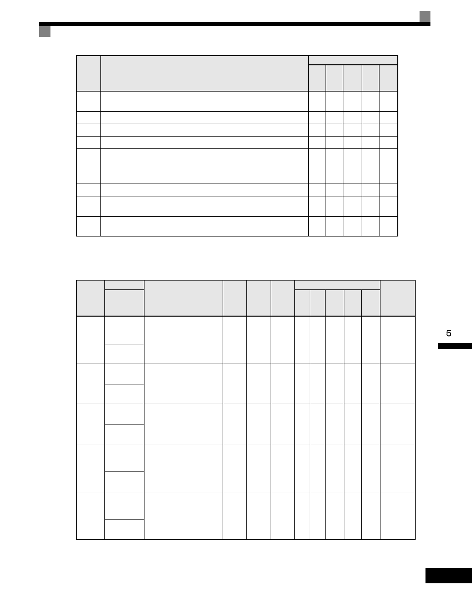
User parameters for analog inputs are shown in the following table.
1F
Motor overload (OL1, including OH3) pre-alarm (ON: 90% or more of the
detection level)
Yes
Yes
Yes
Yes
Yes
20
Drive overheat (OH) pre-alarm (ON: Temperature exceeds L8-02 setting)
Yes
Yes
Yes
Yes
Yes
30
During torque limit (current limit) (ON: During torque limit)
No
No
Yes
Yes
Yes
31
During speed limit (ON: During speed limit)
No
No
No
Yes
Yes
32
Speed control circuit operating for torque control (except when stopped).
The external torque reference will be limited if torque control is selected (internal
torque reference < external torque reference).
Output when the motor is rotating at the speed limit.
No
No
No
Yes
Yes
33
Zero-servo end (ON: Zero-servo function completed)
No
No
No
Yes
No
37
During run 2 (ON: Frequency output, OFF: Base block, DC injection braking,
initial excitation, operation stop)
Yes
Yes
Yes
Yes
Yes
38
Drive is Enabled
Closed = During drive enable, when the Drive Enable input is closed.
Yes
Yes
Yes
Yes
Yes
Parameter
Number
Name
Description
Setting
Range
Factory
Setting
Change
during
Operation
Control Methods
MODBUS
Register
Display
V/f
V/f
with
PG
Open
Loop
Vector
1
Flux
Vector
Open
Loop
Vector
2
H3-01
Terminal A1
Signal Level
Selection
Sets the signal level of
terminal A1.
0: 0 to 10Vdc
1: -10 to +10Vdc
[11-bit plus polarity sign]
0 to 1
0
No
A
A
A
A
A
410H
Term A1
Signal
H3-02
Terminal A1
Gain Setting
Sets the output level when
10V is input, as a percentage
of the maximum output
frequency (E1-04).
0.0
to
1000.0
100.0%
Yes
A
A
A
A
A
411H
Terminal A1
Gain
H3-03
Terminal A1
Bias Setting
Sets the output level when 0V
is input, as a percentage of the
maximum output frequency
(E1-04).
-100.0
to
+100.0
0.0%
Yes
A
A
A
A
A
412H
Terminal A1
Bias
H3-04
Terminal A3
Signal Level
Selection
Sets the signal level of
terminal A3.
0: 0 to 10Vdc
1: -10 to +10Vdc
0 to 1
0
No
A
A
A
A
A
413H
Term A3
Signal
H3-05
Terminal A3
Function
Selection
[Refer to table "H3-05, H3-09
Settings" for multi-function
selections]
0 to 1F
2
No
A
A
A
A
A
414H
Terminal A3
Sel
Setting
Value
Function
Control Methods
V/f
V/f
with
PG
Open
Loop
Vector
1
Flux
Vector
Open
Loop
Vector
2