Related parameters, Time chart, Related parameters time chart – Yaskawa G7 Drive User Manual
Page 288
Input Terminal Functions
6-
71
Stopping Acceleration and Deceleration (Acceleration/Deceleration
Ramp Hold)
The acceleration/deceleration ramp hold function stops acceleration and deceleration, stores the output fre-
quency at that point in time, and then continues operation.
Set one of the parameters H1-01 to H1-10 (multi-function contact input terminal S3 to S12 function selection)
to A (acceleration/deceleration ramp hold) to stop acceleration and deceleration when the terminal is turned
ON and to store the output frequency at that point in time. Acceleration and deceleration will restart when the
terminal is turned OFF.
If d4-01 is set to 1 and the Acceleration/Deceleration Ramp Hold command is input, the output frequency is
still stored even after the power supply is turned OFF.
Related Parameters
Time Chart
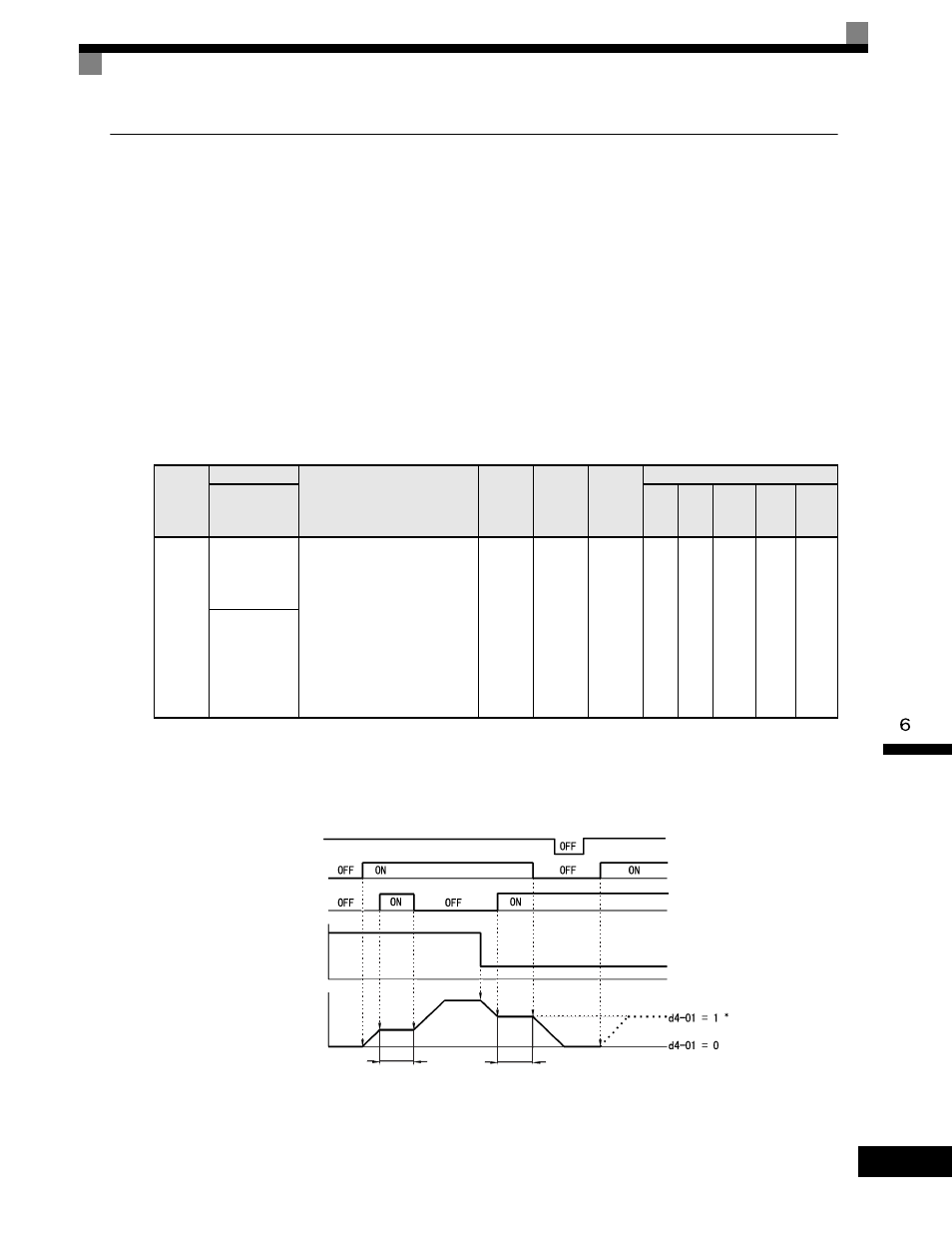
The time chart when using Acceleration/Deceleration Ramp Hold commands is given below.
Fig 6.49 Acceleration/Deceleration Ramp Hold
Parameter
Number
Name
Description
Setting
Range
Factory
Setting
Change
during
Operation
Control Methods
Display
V/f
V/f
with
PG
Open
Loop
Vector
1
Flux
Vector
Open
Loop
Vector
2
d4-01
Frequency
Reference Hold
Function
Selection
This parameter is used to retain
the held frequency reference in
U1-01 (d1-01) when power is
removed. This function is
available when the multi-function
inputs “accel/decel ramp hold” or
“up/down” commands are
selected (H1-XX = A or 10 and
11).
0: Disabled
1: Enabled
0 to 1
0
No
A
A
A
A
A
MOP Ref
Memory
Power supply
Forward/Stop
Acceleration/Deceleration
Ramp Hold
Frequency reference
Output frequency
Hold
Hold