Protective and diagnostic functions, Fault detection, Fault detection -2 – Yaskawa G7 Drive User Manual
Page 383
7
-2
Protective and Diagnostic Functions
This section describes the alarm functions of the Drive. The alarm functions include fault detection, alarm
detection, operation error detection, and autotuning error detection.
Fault Detection
When the Drive detects a fault, the fault contact output operates, and the Drive output is shut OFF causing the
motor to coast to a stop. (The stopping method can be selected for some faults, and the selected stopping
method will be used with these faults.) A fault code is displayed on the Digital Operator.
When a fault has occurred, refer to the following table to identify and correct the cause of the fault.
Use one of the following methods to reset the fault after restarting the Drive:
•
Set a multi-function contact input (H1-01 to H1-05) to 14 (Fault Reset) and turn ON the fault reset signal.
•
Press the RESET Key on the Digital Operator.
•
Turn the main circuit power supply OFF and then ON again.
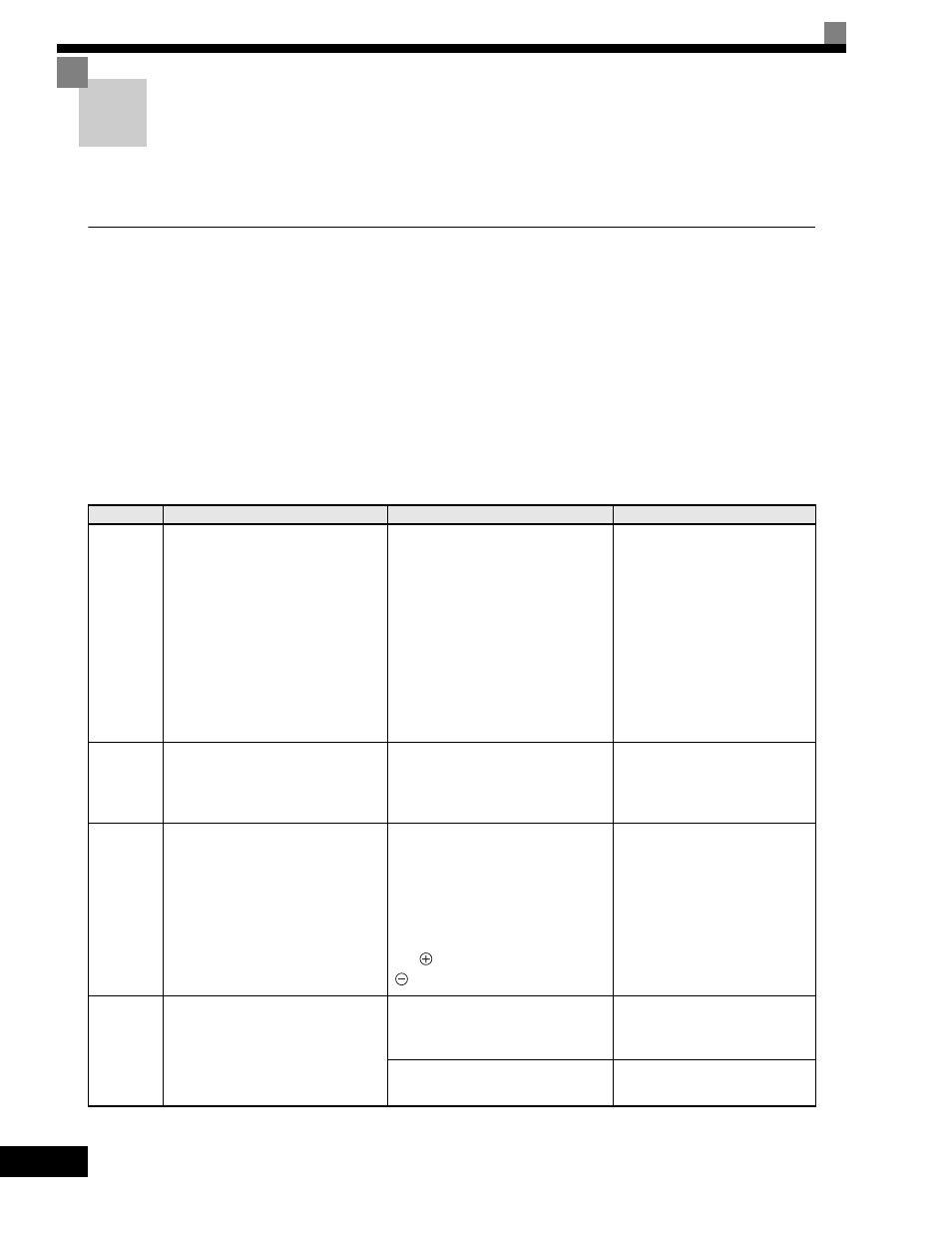
Table 7.1 Fault Displays and Processing
Display
Meaning
Probable Causes
Corrective Actions
OC
Over Cur-
rent
Overcurrent
The Drive output current exceeded the
overcurrent detection level. (200% of
rated current)
• A short-circuit or ground fault
occurred at the Drive output. (A
short or ground fault can be caused
by motor burn damage, worn insu-
lation, or a damaged cable.)
• The load is too large or the accelera-
tion/deceleration time is too short.
• A special-purpose motor or motor
with a capacity too large for the
Drive is being used.
• A magnetic switch was switched at
the Drive output.
Reset the fault after correcting its
cause.
GF
Ground
Fault
Ground Fault
The ground fault current at the Drive
output exceeded approximately 50%
of the Drive rated output current.
A ground fault occurred at the Drive
output. (A ground fault can be caused
by motor burn damage, worn insula-
tion, or a damaged cable.)
Reset the fault after correcting its
cause.
PUF
Main IBGT
Fuse
Blown
Fuse Blown
The fuse in the main circuit is blown.
The output transistor has failed
because of a short-circuit or ground
fault at the Drive output.
Check whether there is a short-circuit
between the following terminals. A
short-circuit will damage the output
transistor:
B1 (
3)
←→ U/T1, V/T2, W/T3
←→ U/T1, V/T2, W/T3
Replace the Drive after correcting
the cause.
OV
DC Bus
Fuse Open
Main Circuit Overvoltage
The main circuit DC voltage exceeded
the overvoltage detection level.
200-240 V class: Approx. 410 V
380-380 V class: Approx. 820 V
The deceleration time is too short and
the regenerative energy from the
motor is too large.
Increase the deceleration time or
connect a braking resistor (or
Braking Resistor Unit).
The power supply voltage is too high.
Decrease the voltage so it's within
specifications.