User parameters, User parameters -20 – Yaskawa G7 Drive User Manual
Page 443
10
-20
User Parameters
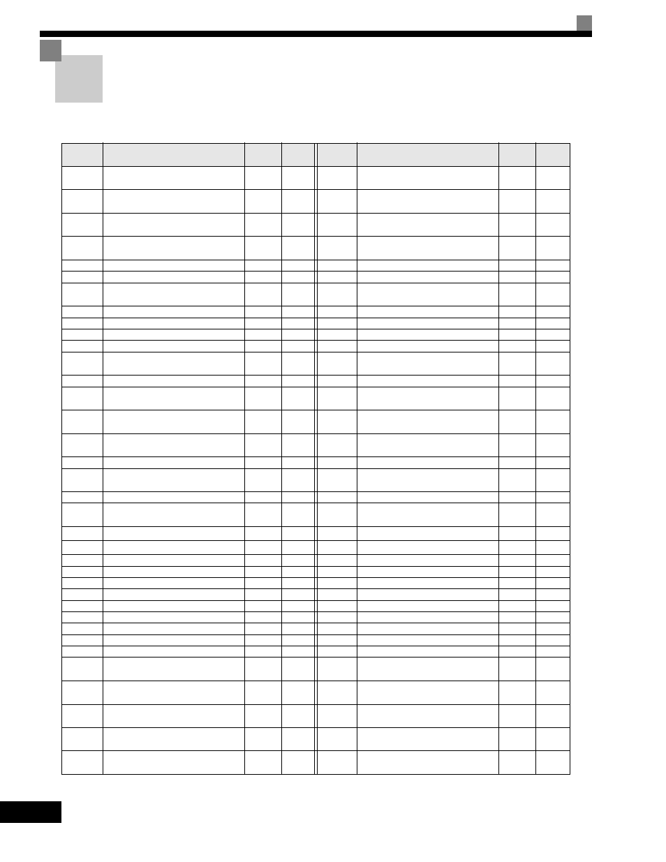
Factory settings are given in the following table. These setting are for a 200-240 V Class Drive of 0.4 kW
set to factory set control method (open-loop vector control).
Table 10.7 User Parameters
No.
Name
Factory
Setting
Setting
No.
Name
Factory
Setting
Setting
A1-00
Language selection for digital
operator display
1
*1
b5-11
PID reverse output selection
0
A1-01 Parameter access level
2
b5-12
Selection of PID feedback com-
mand loss detection
0
A1-02 Control method selection
2
*1
b5-13
PID feedback command loss detec-
tion level
0
A1-03 Initialize
0
b5-14
PID feedback command loss detec-
tion time
1.0
A1-04 Password
0
b5-15
PID sleep function operation level
0.0
A1-05 Password setting
0
b5-16
PID sleep operation delay time
0.0
A2-01 to
A2-32
User setting parameters
-
b5-17
Acceleration/deceleration time for
PID reference
0.0
b1-01
Reference selection
1
b6-01
Dwell frequency at start
0.0
b1-02
Operation method selection
1
b6-02
Dwell time at start
0.0
b1-03
Stopping method selection
0
b6-03
Dwell frequency at stop
0.0
b1-04
Prohibition of reverse operation
0
b6-04
Dwell time at stop
0.0
b1-05
Operation selection for setting E1-
09 or less
0
b7-01
Droop control gain
0.0
b1-06
Read sequence input twice
1
b7-02
Droop control delay time
0.05
b1-07
Operation selection after switching
to remote mode
0
b8-01
Energy-saving mode selection
0
b1-08
Run command selection in pro-
gramming modes
0
b8-02
Energy-saving gain
1.0
*4
b2-01
Zero speed level (DC injection
braking starting frequency)
0.5
b8-03
Energy-saving filter time constant
0.50
*5
b2-02
DC injection braking current
50
b8-04
Energy-saving coefficient
*6
b2-03
DC injection braking time at start
0.00
b8-05
Power detection filter time con-
stant
20
b2-04
DC injection braking time at stop
0.50
b8-06
Search operation voltage limiter
0
b2-08
Magnetic flux compensation vol-
ume
0
b9-01
Zero-servo gain
5
b3-01
Speed search selection
2
*2 *3
b9-02
Zero-servo completion width
10
b3-02
Speed search operating current
100
*2
C1-01 Acceleration time 1
10.0
b3-03
Speed search deceleration time
2.0
C1-02 Deceleration time 1
10.0
b3-05
Speed search wait time
0.2
C1-03 Acceleration time 2
10.0
b4-01
Timer function ON-delay time
0.0
C1-04 Deceleration time 2
10.0
b4-02
Timer function OFF-delay time
0.0
C1-05 Acceleration time 3
10.0
b5-01
PID control mode selection
0
C1-06 Deceleration time 3
10.0
b5-02
Proportional gain (P)
1.00
C1-07 Acceleration time 4
10.0
b5-03
Integral (I) time
1.0
C1-08 Deceleration time 4
10.0
b5-04
Integral (I) limit
100.0
C1-09 Emergency stop time
10.0
b5-05
Derivative (D) time
0.00
C1-10 Accel/decel time setting unit
1
b5-06
PID limit
100.0
C1-11
Accel/decel time switching fre-
quency
0.0
b5-07
PID offset adjustment
0.0
C2-01
S-curve characteristic time at
acceleration start
0.20
b5-08
PID primary delay time constant
0.00
C2-02
S-curve characteristic time at
acceleration end
0.20
b5-09
PID output characteristics selec-
tion
0
C2-03
S-curve characteristic time at
deceleration start
0.20
b5-10
PID output gain
1.0
C2-04
S-curve characteristic time at
deceleration end
0.00