Related parameters – Yaskawa G7 Drive User Manual
Page 246
Adjusting Frequency References
6-
29
Adjusting Frequency Reference Using Pulse Train Inputs
The frequency reference can be adjusted when b1-01 (Reference Selection) is set to 4 (Pulse Train Input). Set
the pulse frequency in parameter H6-02 to 100% reference, and then adjust the gain and bias accordingly
using H6-03 and H6-04.
Related Parameters
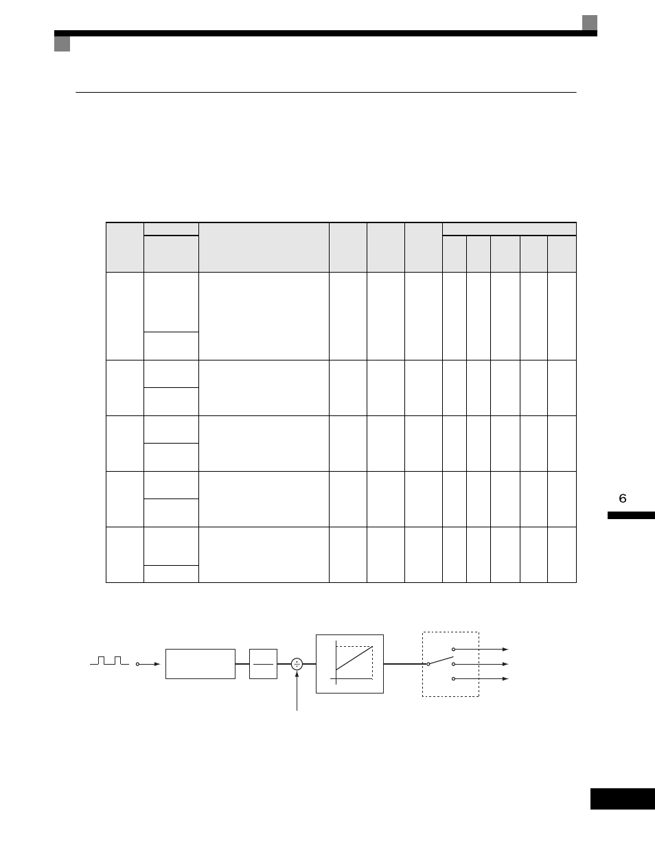
The following diagram shows the method for adjusting the frequency reference using pulse inputs.
Fig 6.29 Frequency Reference Adjustments Using Pulse Train Inputs
Parameter
Number
Name
Description
Setting
Range
Factory
Setting
Change
during
Operation
Control Methods
Display
V/f
V/f
with
PG
Open
Loop
Vector
1
Flux
Vector
Open
Loop
Vector
2
H6-01
Terminal RP
Pulse Train
Input
Function
Selection
Selects the function of pulse train
terminal RP.
0: Frequency reference
1: PID feedback value
2: PID setpoint value
0 to 2
0
No
A
A
A
A
A
Pulse Input
Sel
H6-02
Pulse Train
Input Scaling Sets the number of pulses (in Hz)
that is equal to the maximum output
frequency E1-04.
1000
to
32000
1440Hz
Yes
A
A
A
A
A
Pulse In
Scaling
H6-03
Pulse Train
Input Gain
Sets the output level when the pulse
train input is at 100% as a
percentage of maximum output
frequency E1-04.
0.0
to
1000.0
100.0%
Yes
A
A
A
A
A
Pulse Input
Gain
H6-04
Pulse Train
Input Bias
Sets the output level when the pulse
train input is 0Hz as a percentage of
maximum output frequency E1-04.
-100.0
to
100.0
0.0%
Yes
A
A
A
A
A
Pulse Input
Bias
H6-05
Pulse Train
Input Filter
Time
Sets the pulse train input filter time
constant in seconds.
0.00
to
2.00
0.10sec
Yes
A
A
A
A
A
Pulse In Filter
RP
Cycle
measurement
Filter
H6-05
H6-01
Master speed
frequency
PID feedback
PID target value
=0
=2
=1
Scaling using H6-02
Gain and bias
Pulse
1
1+sT
0%
H6-04
H6-03
100%