Multi-function contact inputs (h1-01 to h1-10) – Yaskawa G7 Drive User Manual
Page 277
6
-60
* 1. The factory setting will change when the control method is changed (Open-loop vector control 1 factory settings are given).
* 2. The factory setting will change when the control method is changed. Set to “3” in V/f with PG.
* 3. Factory settings depend on Drive capacity (The values shown are for a 200-240V Class Drive for 0.4kW).
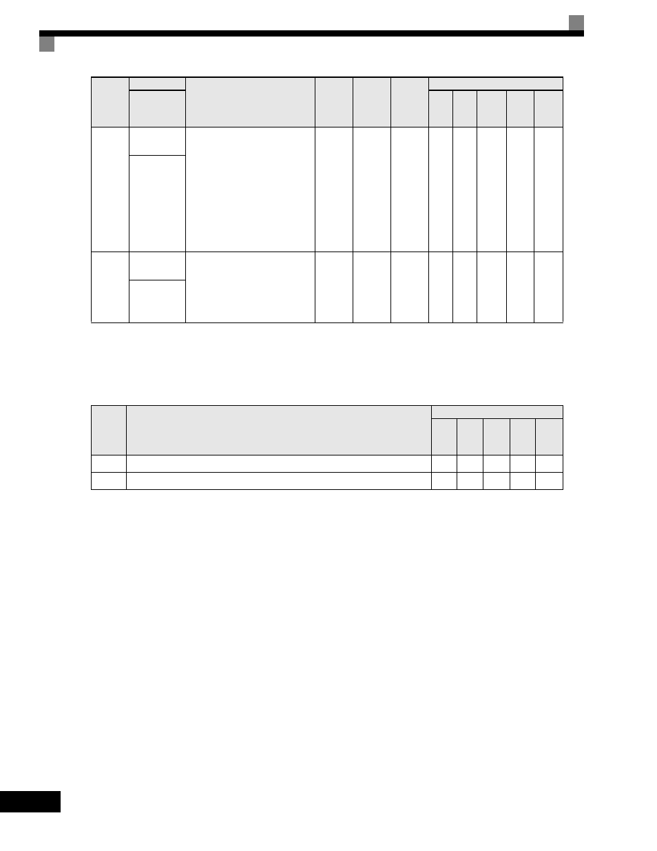
Multi-function Contact Inputs (H1-01 to H1-10)
L2-03
Min. base-
block time
Sets the Drive's minimum base-
block time in units of one second,
when the Drive is restarted after
power loss ridethrough.
Sets the time to approximately 0.7
times the motor secondary circuit
time parameter.
When an overcurrent or overvolt-
age occurs when starting a speed
search or DC injection braking,
increase the set values.
0.1 to
5.0
0.5sec
*3
No
A
A
A
A
A
PwrL Base-
block t
L2-04
Voltage recov-
ery time
Sets the time required to return the
Drive output voltage to normal
voltage at the completion of a speed
search, in units of one second.
Sets the time required to recover
from 0Vto the maximum voltage.
0.0 to
5.0
0.3sec
*3
No
A
A
A
A
A
PwrL V/F
Ramp t
Setting
Value
Function
Control Methods
V/f
V/f
with
PG
Open
Loop
Vector
1
Flux
Vector
Open
Loop
Vector
2
61
External search command 1 (ON: Speed search from maximum output frequency)
Yes
No
Yes
No
Yes
62
External search command 2 (ON: Speed search from set frequency)
Yes
No
Yes
No
Yes
Parameter
Number
Name
Description
Setting
Range
Factory
Setting
Change
during
Operation
Control Methods
Display
V/f
V/f
with
PG
Open
Loop
Vector
1
Flux
Vector
Open
Loop
Vector
2