Installing and wiring option cards, Option card models and specifications, Option card models and specifications -31 – Yaskawa G7 Drive User Manual
Page 62: Installing and wiring option cards -31
Installing and Wiring Option Cards
2-
31
Installing and Wiring Option Cards
Option Card Models and Specifications
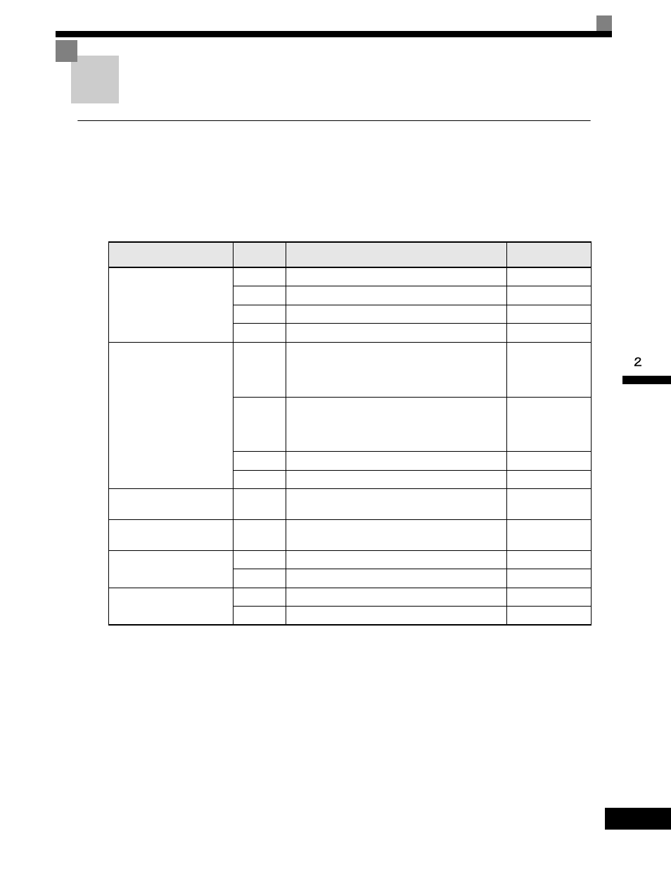
Up to three Option Cards can be mounted in the Drive. You can mount up one card into each of the three
places on the controller card (A, C, and D) shown in Fig 2.18.
Table 2.14 lists the type of Option Cards and their specifications.
Table 2.14 Option Card Specifications
Card
Model
Specifications
Mounting
Location
PG Speed Control Cards
PG-A2
Serial open-collector/complimentary inputs
A
PG-B2
Phase A/B complimentary inputs
A
PG-D2
Single line-driver inputs
A
PG-X2
Phase A/B line-driver inputs
A
Speed Reference Cards
AI-14U
Input signal levels
0 to 10 V DC (20 k
Ω), 1 channel
4 to 20 mA (250
Ω), 1 channel
Input resolution: 14-bit
C
AI-14B
Input signal levels
0 to 10 V DC (20 k
Ω)
4 to 20 mA (250
Ω), 3 channels
Input resolution: 13-bit with sign bit
C
DI-08
8-bit digital speed reference setting
C
DI-16H2
16-bit digital speed reference setting
C
DeviceNet Communications
Card
SI-N
DeviceNet communications support
C
Profibus-DP Communica-
tions Card
SI-P
Profibus-DP communications support
C
Analog Monitor Card
AO-08
8-bit analog outputs, 2 channels
D
AO-12
12-bit analog outputs, 2 channels
D
Digital Output Card
DO-08
Six photocoupler outputs and 2 relay outputs
D
DO-02C
2 relay outputs
D