Cimr-g7u20p4 to 2015 and 40p4 to 4015, Cimr-g7u2018, 2022, and 4018 to 4045, Cimr-g7u2030 to 2110 – Yaskawa G7 Drive User Manual
Page 46: Cimr-g7u4055 to 4300, Standard connection diagrams
Wiring Main Circuit Terminals
2-
15
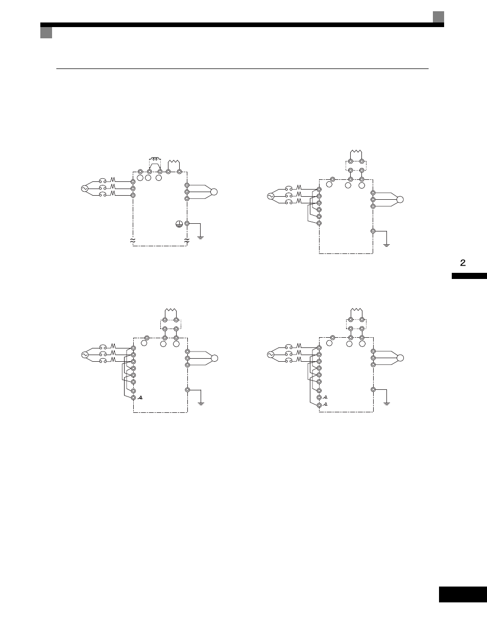
Standard Connection Diagrams
Standard Drive connection diagrams are shown in Fig 2.4. These are the same for both 208-240 Vac and 480
Vac Drives. The connections depend on the Drive capacity.
Control power is supplied internally from the main circuit DC power supply for all Drive models.
Fig 2.4 Main Circuit Terminal Connections
CIMR-G7U20P4 to 2015 and 40P4 to
4015
Be sure to remove the short-circuit bar before connecting the DC
link choke.
CIMR-G7U2018, 2022, and 4018 to 4045
The DC link choke is built in.
CIMR-G7U2030 to 2110
CIMR-G7U4055 to 4300
+ 1 + 2 B1 B2
R/L1
S/L2
T/L3
U/T1
V/T2
IM
W/T3
−
DC link choke
(optional)
3-phase 200-240Vac
(380-480 Vac)
Braking Resistor
Unit (optional)
+ 1
+ 3
R/L1
S/L2
T/L3
U/T1
V/T2
IM
W/T3
R1/L11
S1/L21
T1/L31
−
Braking Unit
(optional)
Braking Resistor
Unit (optional)
3-phase 200-240
Vac(380-480 Vac)
+ 1
+ 3
R/L1
S/L2
T/L3
U/T1
V/T2
IM
W/T3
R1/L11
S1/L21
T1/L31
−
/l2
r/l1
3-phase
200-240Vac
Braking Unit
(optional)
Braking Resistor
Unit (optional)
+ 1
+ 3
R/L1
S/L2
T/L3
U/T1
V/T2
IM
W/T3
R1/L11
S1/L21
T1/L31
−
200/l
2
200
400/l
2
400
r/l1
3-phase 380-480 Vac
Braking Unit
(optional)
Braking Resistor
Unit (optional)