Related parameters – Yaskawa G7 Drive User Manual
Page 346
Individual Functions
6-
129
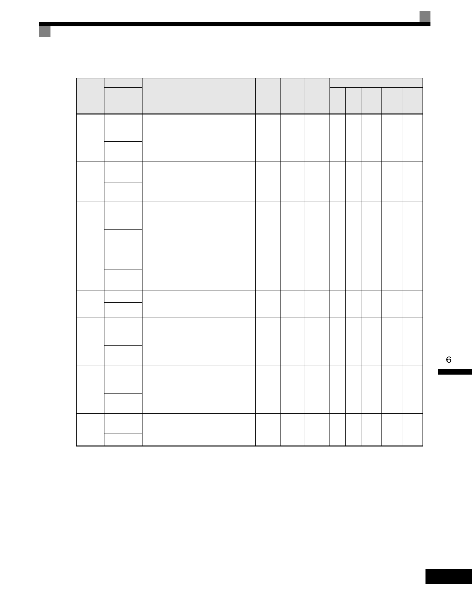
Related Parameters
* 1. Factory settings will change depending on the control mode.
* 2. The setting range becomes 1.00 to 300.0 when using controls modes Flux Vector or Open Loop Vector 2.
Parameter
Number
Name
Description
Setting
Range
Factory
Setting
Change
during
Operation
Control Methods
Display
V/f
V/f
with
PG
Open
Loop
Vector
1
Flux
Vector
Open
Loop
Vector
2
C5-01
ASR
Proportional
Gain 1
Sets the proportional gain of the speed
control loop (ASR)
0.00 to
300.00
*2
20.00
*1
Yes
No
A
No
A
A
ASR P Gain
1
C5-02
ASR Integral
Time 1
Sets the integral time of the speed control
loop (ASR)
0.000
to
10.000
0.500
sec
*1
Yes
No
A
No
A
A
ASR I Time
1
C5-03
ASR
Proportional
Gain 2
Sets the speed control gain 2 and integral
time 2 of the speed control loop (ASR).
Note: Adjustment is not normally required.
0.00
to
300.00
*2
20.00
*1
Yes
No
A
No
A
A
ASR P Gain
2
C5-04
ASR Integral
Time 2
0.000
to
10.000
0.500
sec
*1
Yes
No
A
No
A
A
ASR I Time
2
C5-05
ASR Limit
Sets the upper limit for the speed control
loop (ASR) as a percentage of the
maximum output frequency (E1-04).
0.0
to
20.0
5.0%
No
No
A
No
No
No
ASR Limit
C5-06
ASR Primary
Delay Time
Constant
Sets the filter time constant for the time
from the speed loop to the torque command
output.
0.000
to
0.500
0.004
*1
No
No
No
No
A
A
ASR Delay
Time
C5-07
ASR Gain
Switching
Frequency
Sets the frequency for switching between
Proportional Gain 1, 2 and Integral Time 1,
2.
0.0
to
400.0
0.0
No
No
No
No
A
A
ASR Gain
SW Freq
C5-08
ASR Integral
Limit
Sets the ASR integral upper limit and rated
load as a percentage of maximum output
frequency (E1-04).
0 to 400
400
No
No
No
No
A
A
ASR I Limit