Yaskawa G7 Drive User Manual
Page 66
Installing and Wiring Option Cards
2-
35
PG-X2
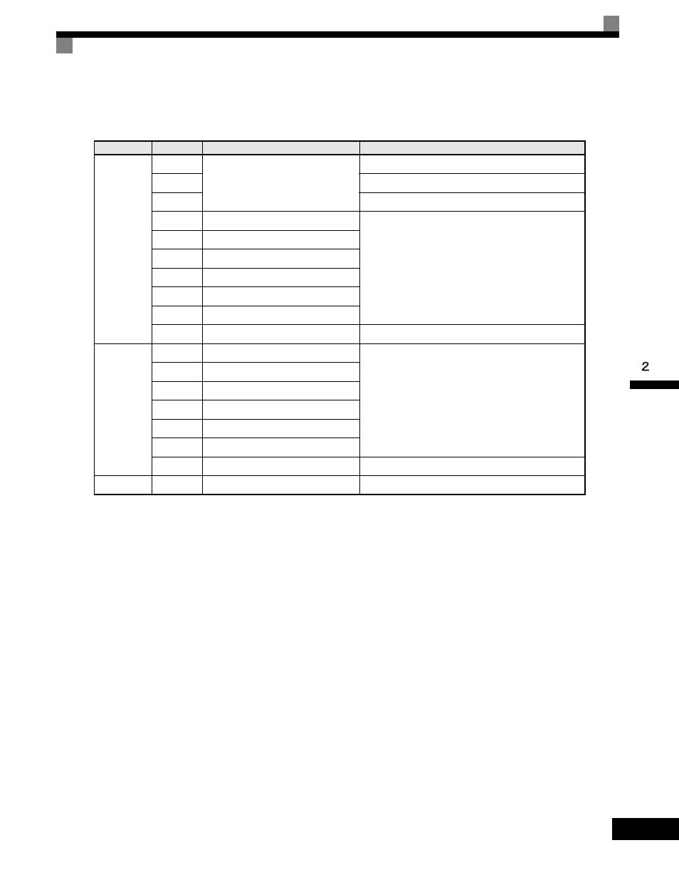
The terminal specifications for the PG-X2 are given in the following table.
* 5 Vdc and 12 Vdc cannot be used at the same time.
Table 2.18 PG-X2 Terminal Specifications
Terminal
No.
Contents
Specifications
TA1
1
Power supply for pulse generator
12 Vdc (±5%), 200 mA max.*
2
0 Vdc (GND for power supply)
3
5 Vdc (±5%), 200 mA max.*
4
A-phase + input terminal
Line driver input (RS-422 level input)
Maximum response frequency: 300 kHz
5
A-phase - input terminal
6
B-phase + input terminal
7
B-phase - input terminal
8
Z-phase + input terminal
9
Z-phase - input terminal
10
Common terminal
0 Vdc (GND for power supply)
TA2
1
A-phase + output terminal
Line driver output (RS-422 level output)
2
A-phase - output terminal
3
B-phase + output terminal
4
B-phase - output terminal
5
Z-phase + output terminal
6
Z-phase - output terminal
7
Control circuit common
Control circuit GND
TA3
(E)
Shield connection terminal
-