Wiring, Wiring the pg-a2, Wiring -36 – Yaskawa G7 Drive User Manual
Page 67
2
-36
Wiring
Wiring examples are provided in the following illustrations for the Control Cards.
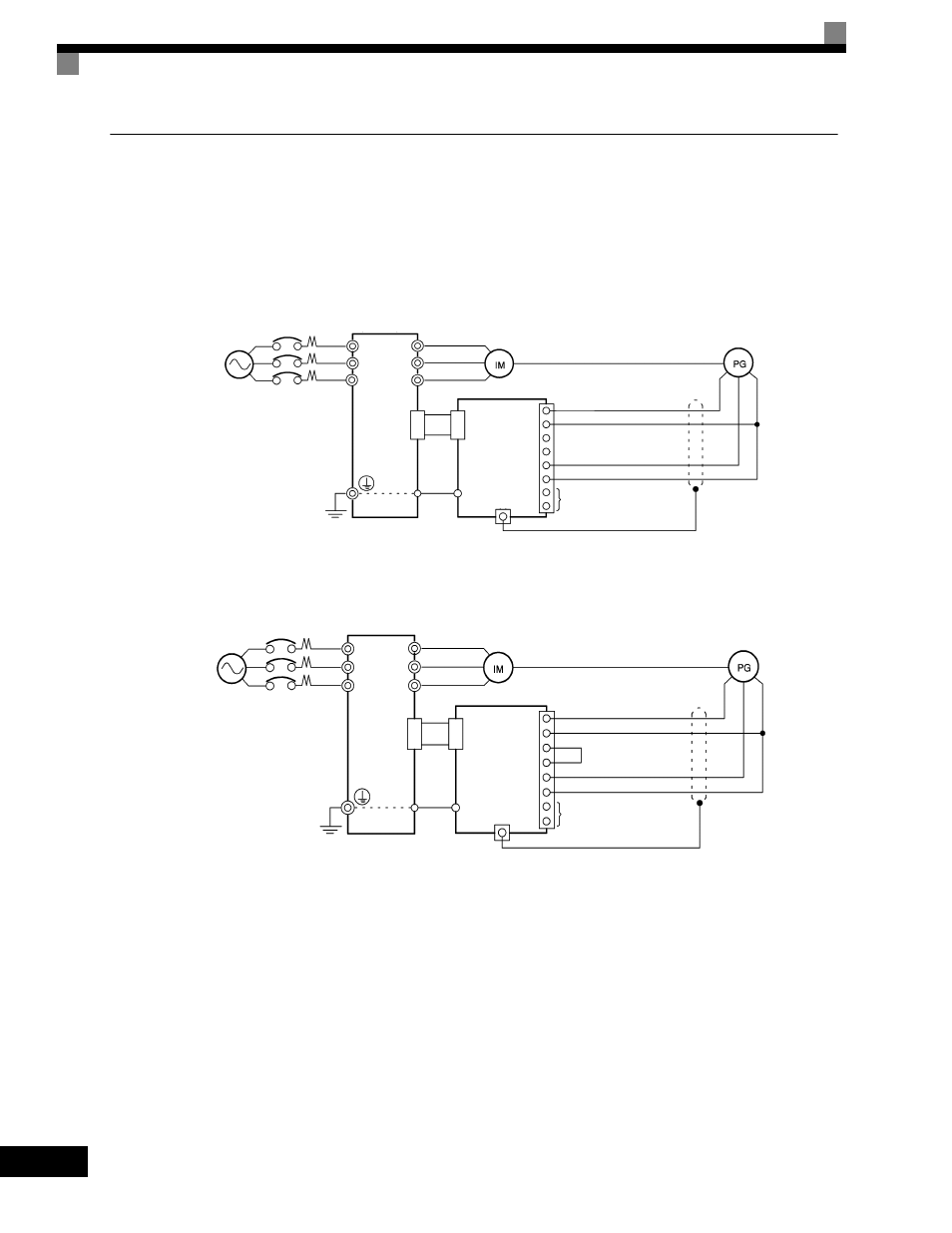
Wiring the PG-A2
Wiring examples are provided in the following illustrations for the PG-A2.
Fig 2.19 Wiring a 12 V Voltage Input
•
Shielded twisted-pair wires must be used for signal lines.
•
Do not use the pulse generator's power supply for anything other than the pulse generator (encoder).
Using it for another purpose can cause malfunctions due to noise.
•
The length of the pulse generator's wiring must not be more than 100 meters (328 ft).
Fig 2.20 Wiring an Open-collector Input
Three-phase, 200-240
Vac (380-480 Vac)
Drive
+12 Vdc power supply
0 Vdc power supply
12 Vdc voltage input (A/B phase)
Pulse 0 Vdc
Pulse monitor output
R/L1
V/T2
W/T3
U/T1
V/T2
W/T3
4CN
4CN
E
E
1
2
3
4
5
6
7
8
TA1
TA2 (E)
PG-A2
Three-phase, 200-
240 Vac (380-480 Vac)
Drive
+12 Vdc power supply
0 Vdc power supply
Open collector output (A/B phase)
Pulse 0 Vdc
Pulse monitor output
R/L1
V/T2
W/T3
U/T1
V/T2
W/T3
4CN
4CN
E
E
1
2
3
4
5
6
7
8
TA1
TA2 (E)
PG-A2