Yaskawa G7 Drive User Manual
Page 157
5
-46
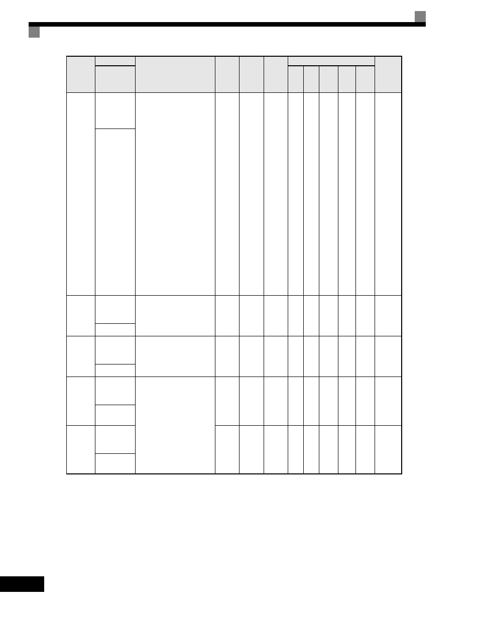
F4-04
AO-08/
AO-12
Channel 2
Gain
Sets the channel 2 gain.
In order to adjust the
meter, 100% of the
appropriate output is
multiplied for the gain
setting, and the bias
amount is added and then
output.
See F4-02 when stopped
in Quick, Advanced, or
Verify mode.
-If 05 appears on the
setting screen, then CH1
is used.
See F4-04 when stopped
in Quick, Advanced, or
Verify mode.
-If 06 appears on the
setting screen, then CH2
is used.
Ex: Set F4-04 = 50% to
output 100% at 5.0V
output.
0.0
to
1000.0
50.0%
Yes
A
A
A
A
A
394H
AO Ch2 Gain
F4-05
AO-08/AO-
12 Channel 1
Output Bias
Sets the channel 1 bias
(100%/10V).
Ex: Set F4-05 = 50% to
output 0% at 5.0V output.
-110.0
to
110.0
0.0%
Yes
A
A
A
A
A
395H
AO Ch1 Bias
F4-06
AO-08/AO-
12 Channel 2
Output Bias
Sets the channel 2 bias
(100%/10V).
Ex: Set F4-06 = 50% to
output 0% at 5.0V output.
-110.0
to
110.0
0.0%
Yes
A
A
A
A
A
396H
AO Ch2 Bias
F4-07
AO-12
Channel 1
Signal Level
Sets the range of the voltage
output.
0: 0 to 10Vdc
1: -10 to +10Vdc
0 or 1
0
No
A
A
A
A
A
397H
AO Opt
Level Ch1
F4-08
AO-12
Channel 2
Signal Level
0 or 1
0
No
A
A
A
A
A
398H
AO Opt
Level Ch2
Parameter
Number
Name
Description
Setting
Range
Factory
Setting
Change
during
Operation
Control Methods
MODBUS
Register
Display
V/f
V/f
with
PG
Open
Loop
Vector
1
Flux
Vector
Open
Loop
Vector
2