Connecting the braking resistor (erf) – Yaskawa G7 Drive User Manual
Page 52
Wiring Main Circuit Terminals
2-
21
Connecting the Braking Resistor (ERF)
A Braking Resistor that mounts to the Drive can be used with 200-240 V and 380-480 V Class Drives with
outputs from 0.4 to 3.7 kW.
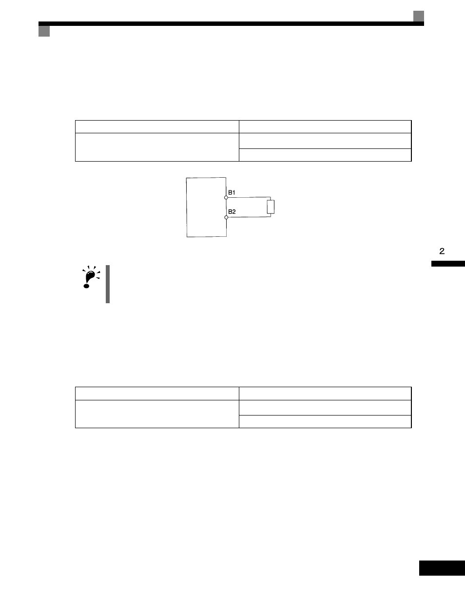
Connect the braking resistor as shown in Fig 2.12.
Fig 2.12 Connecting the Braking Resistor
Connecting the Braking Resistor Unit (LKEB) and Braking Unit (CDBR)
Use the following settings when using a Braking Resistor Unit. Refer to
User Parameters on page
connection methods for a Braking Resistor Unit.
A Braking Resistor that mounts to the Drive can also be used with Drives with outputs from 0.4 to 3.7 kW.
L8-01 is used when a braking resistor without thermal overload relay trip contacts (ERF type mounted to
Drive) is connected.
The Braking Resistor Unit cannot be used and the deceleration time cannot be shortened by the Drive if L3-04
is set to 1 (i.e., if stall prevention is enabled for deceleration).
Table 2.7
L8-01 (Protect selection for internal DB resistor)
1 (Enables overheat protection)
L3-04 (Stall prevention selection during deceleration)
(Select either one of them.)
0 (Disables stall prevention function)
3 (Enables stall prevention function with braking resistor)
IMPORTANT
The braking resistor connection terminals are B1 and B2. Do not connect to any other terminals. Connecting
to any terminals other than B1 or B2 can cause the resistor to overheat, resulting in damage to the
equipment.
Table 2.8
L8-01 (Protect selection for internal DB resistor)
0 (Disables overheat protection)
L3-04 (Stall prevention selection during deceleration)
(Select either one of them.)
0 (Disables stall prevention function)
3 (Enables stall prevention function with braking resistor)
Drive
Braking resistor