Status monitor parameters: u1, U: monitor parameters – Yaskawa G7 Drive User Manual
Page 197
5
-86
U: Monitor Parameters
The following settings are made with the monitor parameters (U parameters): Setting parameters for monitoring in
drive mode.
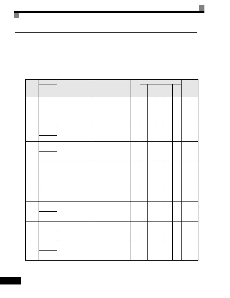
Status Monitor Parameters: U1
The parameters used for monitoring status are listed in the following table.
Parameter
Number
Name
Description
Output Signal Level
During Multi-Function
Analog Output
Min.
Unit
Control Methods
MODBUS
Register
Display
V/f
V/f
with
PG
Open
Loop
Vector
1
Flux
Vector
Open
Loop
Vector
2
U1-01
Frequency
Reference
Frequency reference
(speed command) monitor
when in REMOTE mode,
frequency reference (speed
command) setting location
when in local mode or
b1-01 = 0.*
10V: Maximum Frequency
(possible for -10V thru +10V)
0.01
Hz
A
A
A
A
A
40H
Frequency
Ref
U1-02
Output
Frequency
Output frequency.*
10V: Maximum Frequency
(possible for -10V thru +10V)
0.01
Hz
A
A
A
A
A
41H
Output Freq
U1-03
Output
Current
Output current
10V: Drive Rated Output Current
(output of absolute value of
0V thru +10V possible)
0.1 A
A
A
A
A
A
42H
Output
Current
U1-04
Control
Method
Control method set in
A1-02.
0 = V/F without PG
1 = V/F with PG
2 = Open Loop Vector
3 = Flux Vector
4 = Open Loop Vector 2
No output possible.
-
A
A
A
A
A
43H
Control
Method
U1-05
Motor Speed
Motor speed feedback*
10V: Maximum Frequency
(possible for -10V thru +10V)
0.01
Hz
No
A
A
A
A
44H
Motor Speed
U1-06
Output
Voltage
Output voltage
10V: AC200V (AC400V)
(output of 0V thru +10V)
0.1 V
A
A
A
A
A
45H
Output
Voltage
U1-07
DC bus
Voltage
DC Bus Voltage
10V: DC400V (DC800V)
(output of 0V thru +10V)
1 V
A
A
A
A
A
46H
DC Bus
Voltage
U1-08
Output
Power
Output power
10V: Drive Capacity in kW
(Largest Application Motor
Capacity)
(possible for -10V thru +10V)
0.1
kW
A
A
A
A
A
47H
Output
kWatts