Drive mode indicators, Remote sequence (seq) indicator, Remote reference (ref) indicator – Yaskawa G7 Drive User Manual
Page 77
3
-4
Drive Mode Indicators
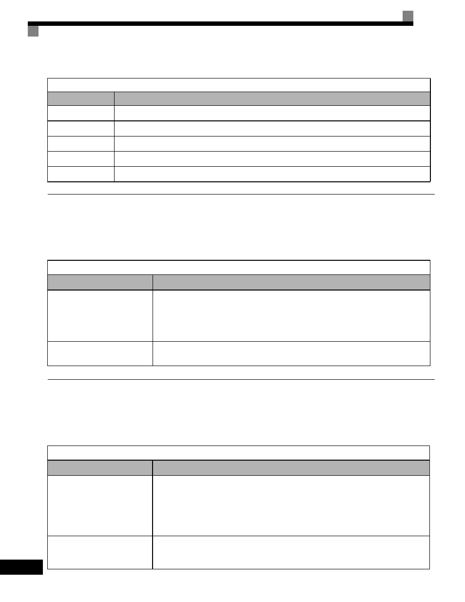
The definition of the Drive mode indicators are shown in Table 3.2.
REMOTE Sequence (SEQ) Indicator
The status of the “REMOTE” Sequence (SEQ) indicator is shown in Table 3.3. This indicator is always “Off” when the Drive is
in the “LOCAL” mode. When the Drive is in the “REMOTE” mode, the SEQ indicator status is dependent on the setting of
parameter b1-02 (Run Command Selection). See Table 3.3.
REMOTE Reference (REF) Indicator
The status of the “REMOTE” Reference (REF) indicator is shown in Table 3.4. This indicator is always “Off” when the Drive is
in the “LOCAL” mode. When the Drive is in the “REMOTE” mode, the REF indicator status is dependent on the setting of
parameter b1-01 (Frequency Reference Selection). See Table 3.4.
Table 3.2 Drive Mode Indicators
Indicator
Definition
FWD
Lit when a forward run command is input.
REV
Lit when a reverse run command is input.
REMOTE SEQ
See Table 3.3.
REMOTE REF
See Table 3.4.
ALARM
Lit when a fault has occurred. Flashes when an Alarm has occurred.
Table 3.3 REMOTE Sequence (SEQ) Indicator
Indicator Status
Condition
On
Parameter b1-02 (Run Command Selection) is set to terminal strip, communications, or an option
board as indicated below:
b1-02 =1 (Terminals)
=2 (Communications)
=3 (Option PCB)
Off
Parameter b1-02 (Run Command Selection) is set to Digital Operator as indicated below:
b1-02=0 (Operator)
Table 3.4 REMOTE Reference (REF) Indicator
Indicator Status
Condition
On
Parameter b1-01 (Frequency Reference Selection) is set to terminal strip, communications, option
board, or pulse train as indicated below:
b1-01 =1 (Terminals)
=2 (Communications)
=3 (Option PCB)
=4 (Pulse Train)
Off
Parameter b1-01 (Frequency Reference Selection) is set to digital
operator as indicated below:
b1-01=0 (Operator)