Pulse train i/o: h6 – Yaskawa G7 Drive User Manual
Page 171
5
-60
Pulse Train I/O: H6
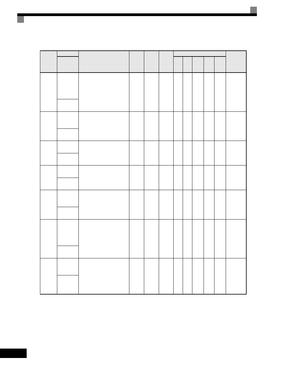
User parameters for pulse I/O are shown in the following table.
Parameter
Number
Name
Description
Setting
Range
Factory
Setting
Change
during
Operation
Control Methods
MODBUS
Register
Display
V/f
V/f
with
PG
Open
Loop
Vector
1
Flux
Vector
Open
Loop
Vector
2
H6-01
Terminal
RP Pulse
Train Input
Function
Selection
Selects the function of pulse
train terminal RP.
0: Frequency reference
1: PID feedback value
2: PID setpoint value
0 to 2
0
No
A
A
A
A
A
42CH
Pulse Input
Sel
H6-02
Pulse Train
Input
Scaling
Sets the number of pulses (in
Hz) that is equal to the
maximum output frequency
E1-04.
1000
to
32000
1440Hz
Yes
A
A
A
A
A
42DH
Pulse In
Scaling
H6-03
Pulse Train
Input Gain
Sets the output level when the
pulse train input is at 100% as a
percentage of maximum output
frequency E1-04.
0.0
to
1000.0
100.0%
Yes
A
A
A
A
A
42EH
Pulse Input
Gain
H6-04
Pulse Train
Input Bias
Sets the output level when the
pulse train input is 0Hz as a
percentage of maximum output
frequency E1-04.
-100.0
to
100.0
0.0%
Yes
A
A
A
A
A
42FH
Pulse Input
Bias
H6-05
Pulse Train
Input Filter
Time
Sets the pulse train input filter
time constant in seconds.
0.00
to
2.00
0.10sec
Yes
A
A
A
A
A
430H
Pulse In
Filter
H6-06
Terminal
MP Pulse
Train
Monitor
Selection
Select the pulse train monitor
output terminal MP function
(value of the xx part of U1-xx).
See Table A2 for the list of U1
monitors.
1, 2, 5,
20, 24,
36
2
Yes
A
A
A
A
A
431H
Pulse Moni
Sel
H6-07
Pulse Train
Monitor
Scaling
Sets the number of output
pulses when the monitor is
100% (in Hz). Set H6-06 to 2,
and H6-07 to 0, to make the
pulse train monitor output
synchronous to the output
frequency.
0
to
32000
1440Hz
Yes
A
A
A
A
A
432H
Pulse Moni
Scale