Yaskawa G7 Drive User Manual
Page 386
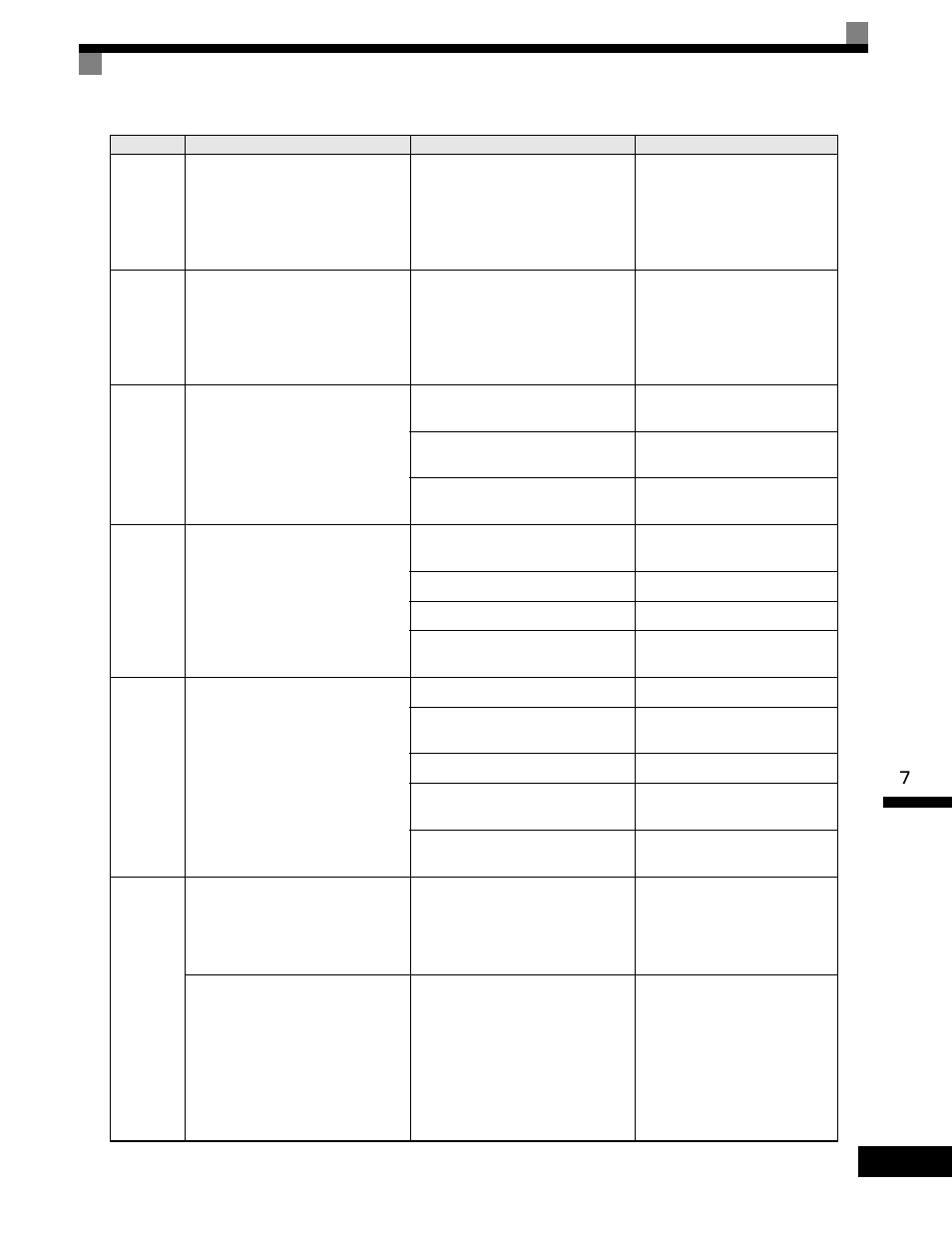
Protective and Diagnostic Functions
7-
5
UL3
Undertorq
Det 1
Undertorque Detected 1
There has been a current less than the
setting in L6-02 for longer than the
setting in L6-03.
-
• Make sure that the settings in
L6-02 and L6-03 are appropri-
ate.
• Check the mechanical system
and correct the cause of the
overtorque.
UL4
Undertorq
Det 2
Undertorque Detected 2
There has been a current less than the
setting in L6-05 for longer than the
setting in L6-06.
-
• Make sure that the current set-
ting in L6-05 and time setting in
L6-06 are appropriate.
• Check the mechanical system
and correct the cause of the
overtorque.
OS
Overspeed
Det
Overspeed
The speed has been greater than the
setting in F1-08 for longer than the
setting in F1-09.
Overshooting/Undershooting are
occurring.
Adjust the gain again.
The reference speed is too high.
Check the reference circuit and
reference gain.
The settings in F1-08 and F1-09 aren't
appropriate.
Check the settings in F1-08 and
F1-09.
PGO
PG Open
PG Disconnection Detected
PG pulses were input when the Drive
was outputting a frequency.
There is a break in the PG wiring.
Fix the broken/disconnected wir-
ing.
The PG is wired incorrectly.
Fix the wiring.
Power isn't being supplied to the PG.
Supply power to the PG properly.
-
Check for open circuit when using
brake (motor).
DEV
Speed
Deviation
Excessive Speed Deviation
The speed deviation has been greater
than the setting in F1-10 for longer
than the setting in F1-11.
The load is too heavy.
Reduce the load.
The acceleration time and deceleration
time are too short.
Lengthen the acceleration time
and deceleration time.
The load is locked.
Check the mechanical system.
The settings in F1-10 and F1-11 aren't
appropriate.
Check the settings in F1-10 and
F1-11.
-
Check for open circuit when using
brake (motor).
CF
Out of
Control
Control Fault
The torque limit was reached continu-
ously for 3 seconds or longer during a
deceleration stop during open-loop
vector control 1.
Motor parameter settings are not cor-
rect.
• Check the motor parameters.
• Perform autotuning.
An error occurred in the speed estima-
tion calculation for open-loop vector
control 2.
Motor parameter settings are not cor-
rect.
Run command was received when the
motor was coasting.
• Perform autotuning.
• Input the run command after the
motor stops.
• Set b3-01 (Speed search selec-
tion) to 1 or 3 (speed search
enabled at startup).
• Refer to Precautions When
Using Open-loop Vector Con-
trol 2 on page 10-4.
Table 7.1 Fault Displays and Processing (Continued)
Display
Meaning
Probable Causes
Corrective Actions