Motor slip compensation: c3 – Yaskawa G7 Drive User Manual
Page 135
5
-24
Motor Slip Compensation: C3
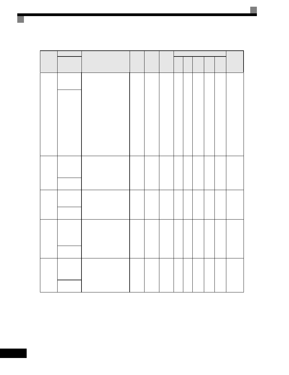
User parameters for slip compensation are shown in the following table.
* The display shows the factory settings for Open Loop Vector. Default settings will change in accordance with the control mode.
Parameter
Number
Name
Description
Setting
Range
Factory
Setting
Change
during
Operation
Control Methods
MODBUS
Register
Display
V/f
V/f
with
PG
Open
Loop
Vector
1
Flux
Vector
Open
Loop
Vector
2
C3-01
Slip
Compensation
Gain
This parameter is used to
increase motor speed to
account for motor slip by
boosting the output
frequency. If the speed is
lower than the frequency
reference, increase C3-01. If
the speed is higher than the
frequency reference, decrease
C3-01.
Note: Adjustment is not
normally required. When
operating in Open Loop
Vector, this parameter
works as a function to set
the proper amount of
gain.
0.0
to
2.5
1.0*
Yes
A
No
A
A
A
20FH
Slip Comp
Gain
C3-02
Slip
Compensation
Primary
Delay Time
This parameter adjusts the
filter on the output of the slip
compensation function.
Increase to add stability,
decrease to improve response.
0
to
10000
200ms*
No
A
No
A
No
No
210H
Slip Comp
Time
C3-03
Slip
Compensation
Limit
This parameter sets the upper
limit for the slip compensation
function. It is set as a
percentage of motor rated slip
(E2-02).
0
to
250
200%
No
A
No
A
No
No
211H
Slip Comp
Limit
C3-04
Slip
Compensation
Selection
During
Regeneration
Determines whether slip
compensation is enabled or
disabled during regenerative
operation.
0: Disabled
1: Enabled
0 or 1
0
No
A
No
A
No
No
212H
Slip Comp
Regen
C3-05
Output
Voltage Limit
Operation
Selection
Determines if the motor
magnetic flux is automatically
decreased when output
voltage saturation occurs.
0: Disabled
1: Enabled
0 or 1
0*
No
No
No
A
A
A
213H
V/f Slip Cmp
Sel