Yaskawa G7 Drive User Manual
Page 154
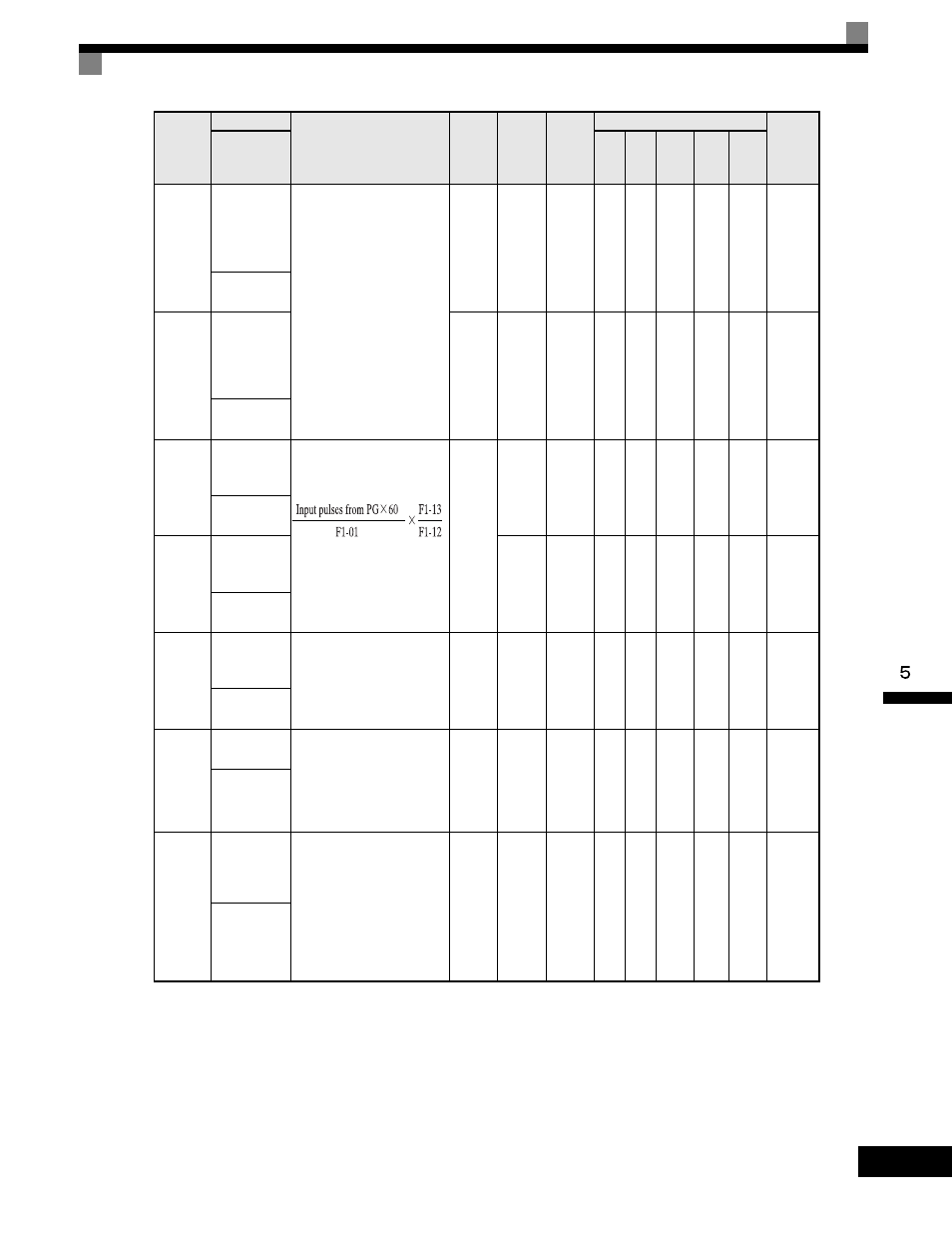
User Parameter Tables
5-
43
*
The factory setting will change when the control method is changed. (Flux vector control factory settings are given.)
*1 Default settings changed based on the initialization mode (o2-09).
F1-10
Excessive
Speed
Deviation
Detection
Level
Configures the speed
deviation fault (DEV)
detection.
DEV fault will occur if the
speed deviation is greater
than the F1-10 setting for a
time longer than F1-11. F1-10
is set as a percentage of the
maximum output frequency
(E1-04).
Speed deviation is the
difference between actual
motor speed and the
frequency reference
command. See F1-04.
0 to 50
10%
No
No
A
No
A
A
389H
PG Deviate
Level
F1-11
Excessive
Speed
Deviation
Detection
Delay Time
0.0
to
10.0
0.5 s
No
No
A
No
A
A
38AH
PG Deviate
Time
F1-12
Number of
PG Gear
Teeth 1
Sets the gear ratio between
the motor shaft and the
encoder (PG).
A gear ratio of 1 will be used
if either of these parameters is
set to 0. This function is not
available in flux vector con-
trol.
0
to
1000
0
No
No
A
No
No
No
38BH
PG # Gear
Teeth1
F1-13
Number of
PG Gear
Teeth 2
0
No
No
A
No
No
No
38CH
PG # Gear
Teeth2
F1-14
PG
Open-circuit
Detection Time
Configures the PG open
(PGO) function. PGO will be
detected if no PG pulses are
detected for a time longer
than F1-14. See F1-02.
0.0
to
10.0
2.0 s
No
No
A
No
A
No
38DH
PGO Detect
Time
F1-21
PG
Parameter 2
Sets the PG pulse count for
Motor-2 (pulse selector,
encoder). Set a value that is
not significantly less than the
pulse count per rotation in
Motor-1.
0
to
60000
1024
*1
No
No
Q
No
Q
No
3B0H
PG Pulses/
Rev 2
F1-22
PG
Rotational
Direction
Setting 2
Sets the direction of rotation
for the PG connected to
Motor-2.
0: From phase-A when
rotating forwards (from
phase-B when in reverse).
1: From phase-B when
rotating forwards (from
phase-A when in reverse).
0 to 1
0
No
No
Q
No
Q
No
3B1H
PG Rotation
Sel2
Parameter
Number
Name
Description
Setting
Range
Factory
Setting
Change
during
Operation
Control Methods
MODBUS
Register
Display
V/f
V/f
with
PG
Open
Loop
Vector
1
Flux
Vector
Open
Loop
Vector
2