Yaskawa G7 Drive User Manual
Page 200
User Parameter Tables
5-
89
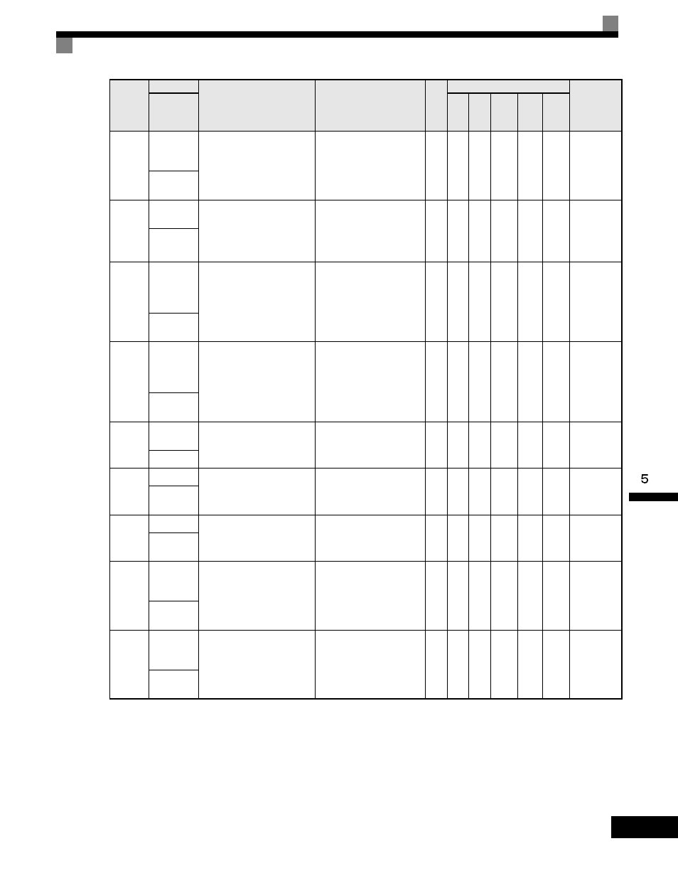
U1-24
PI
Feedback
Value
Feedback signal level when
PID control is used.
10V: Maximum Frequency
(possible for -10V thru +10V)
0.0
1%
A
A
A
A
A
57H
PID
Feedback
U1-25
DI-16H2
Input Status
Reference value from a DI-
16H2 Digital Reference Card.
The value will be displayed in
binary or BCD depending on
user constant F3-01.
No output possible.
-
A
A
A
A
A
58H
DI-16
Reference
U1-26
Output
Voltage
Reference
(Vq)
Internal voltage reference for
motor secondary current
control.
10V: AC200V (AC400)
(possible for -10V thru +10V)
0.1
V
No
No
A
A
A
59H
Voltage Ref
(Vq)
U1-27
Output
Voltage
Reference
(Vd)
Internal voltage reference for
motor excitation current
control.
10V: AC200V (AC400)
(possible for -10V thru +10V)
0.1
V
No
No
A
A
A
5AH
Voltage Ref
(Vd)
U1-28
CPU
Number
Control board hardware
revision.
No output possible.
-
A
A
A
A
A
5BH
CPU ID
U1-29
kWh
Accumulated kilowatt-hours.
No output possible.
0.1
KW
H
A
A
A
A
A
5CH
kWh Lower
4 dig
U1-30
MWh
Accumulated megawatt-hours. No output possible.
M
WH
A
A
A
A
A
5DH
kWh Upper
5 dig
U1-32
ACR
Output of q
Axis
Current control output value
for the motor secondary
current.
10V: 100%
(possible for -10V thru +10V)
0.1
%
No
No
A
A
A
5FH
ACR(q)
Output
U1-33
ACR
Output of d
Axis
Current control output value
for the motor excitation
current.
10V: 100%
(possible for -10V thru +10V)
0.1
%
No
No
A
A
A
60H
ACR(d)
Output
Parameter
Number
Name
Description
Output Signal Level
During Multi-Function
Analog Output
Min.
Unit
Control Methods
MODBUS
Register
Display
V/f
V/f
with
PG
Open
Loop
Vector
1
Flux
Vector
Open
Loop
Vector
2