Main circuit configurations, Drive, Table 2.5 – Yaskawa G7 Drive User Manual
Page 45
2
-14
Main Circuit Configurations
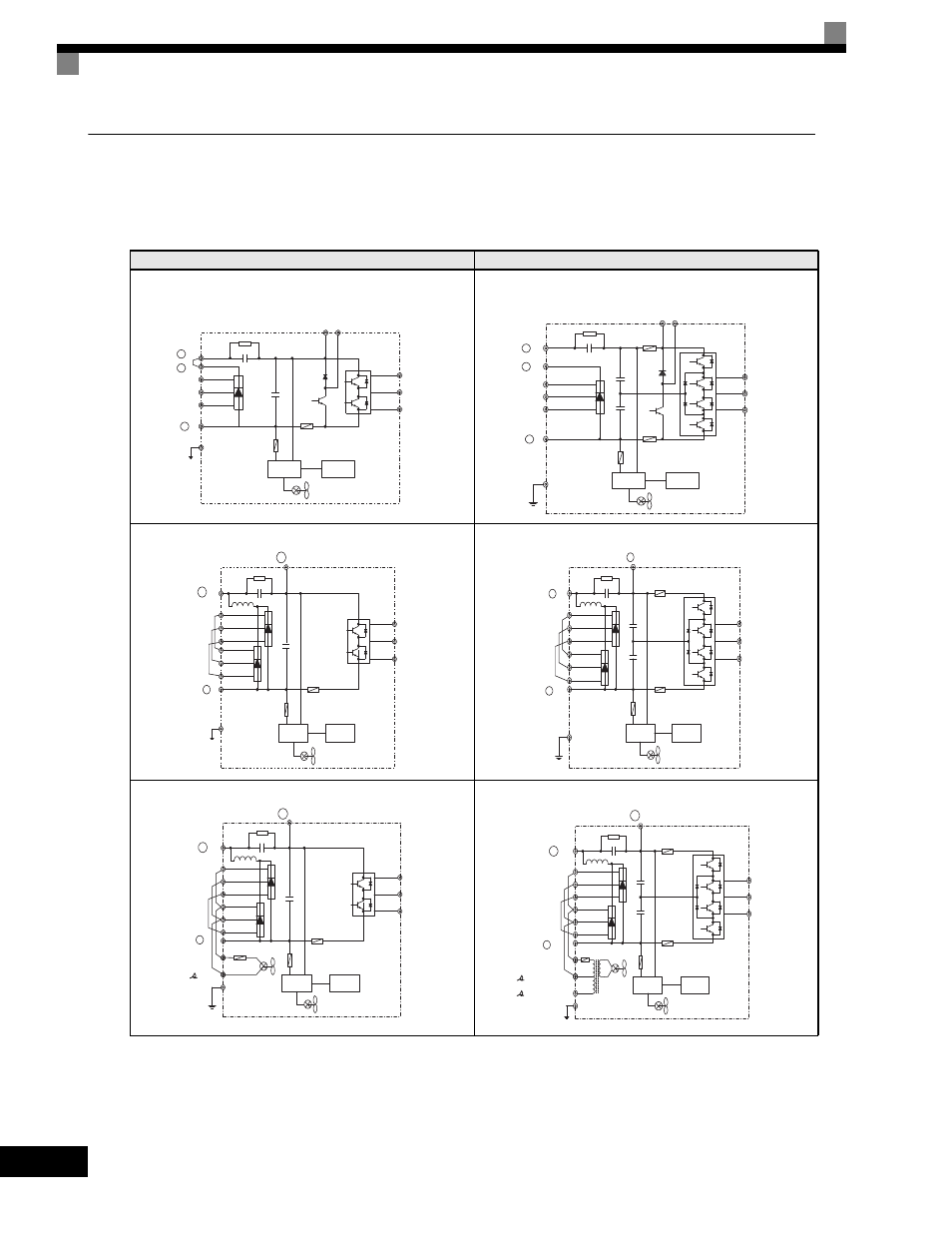
The main circuit configurations of the Drive are shown in Table 2.5.
Table 2.5
Drive
Main Circuit Configurations
Note Consult your Yaskawa representative before using 12-phase rectification.
208-240 Vac
480 Vac
B1 B2
1
+
+ 2
−
CIMR-G7U20P4 to 2015
Power
supply
Control
circuits
R/L1
S/L2
T/L3
U/T1
V/T2
W/T3
U/T1
V/T2
W/T3
1
+
+ 2
R/L1
S/L2
T/L3
−
B1 B2
CIMR-G7U40P4 to 4015
Power
supply
Control
circuits
+ 1
R/L1
S/L2
T/L3
R1/L11
S1/L21
T1/L31
−
+ 3
U/T1
V/T2
W/T3
CIMR-G7U2018, 2022
Power
supply
Control
circuits
U/T1
V/T2
W/T3
1
R/L1
S/L2
T/L3
R1/L11
S1/L21
T1/L31
−
3
+
+
CIMR-G7U4018 to 4045
Power
supply
Control
circuits
+ 1
R/L1
S/L2
T/L3
R1/L11
S1/L21
T1/L31
−
+ 3
U/T1
V/T2
W/T3
/l2
r/
1
l
CIMR-G7U2030 to 2110
Power
supply
Control
circuits
+ 1
+ 3
200/
2
200
l
400/
2
400
l
R/L1
S/L2
T/L3
R1/L11
S1/L21
T1/L31
U/T1
V/T2
W/T3
−
r/
1
l
CIMR-G7U4055 to 4300
Power
supply
Control
circuits