Setting precautions – Yaskawa G7 Drive User Manual
Page 240
Acceleration and Deceleration Characteristics
6-
23
Setting Example
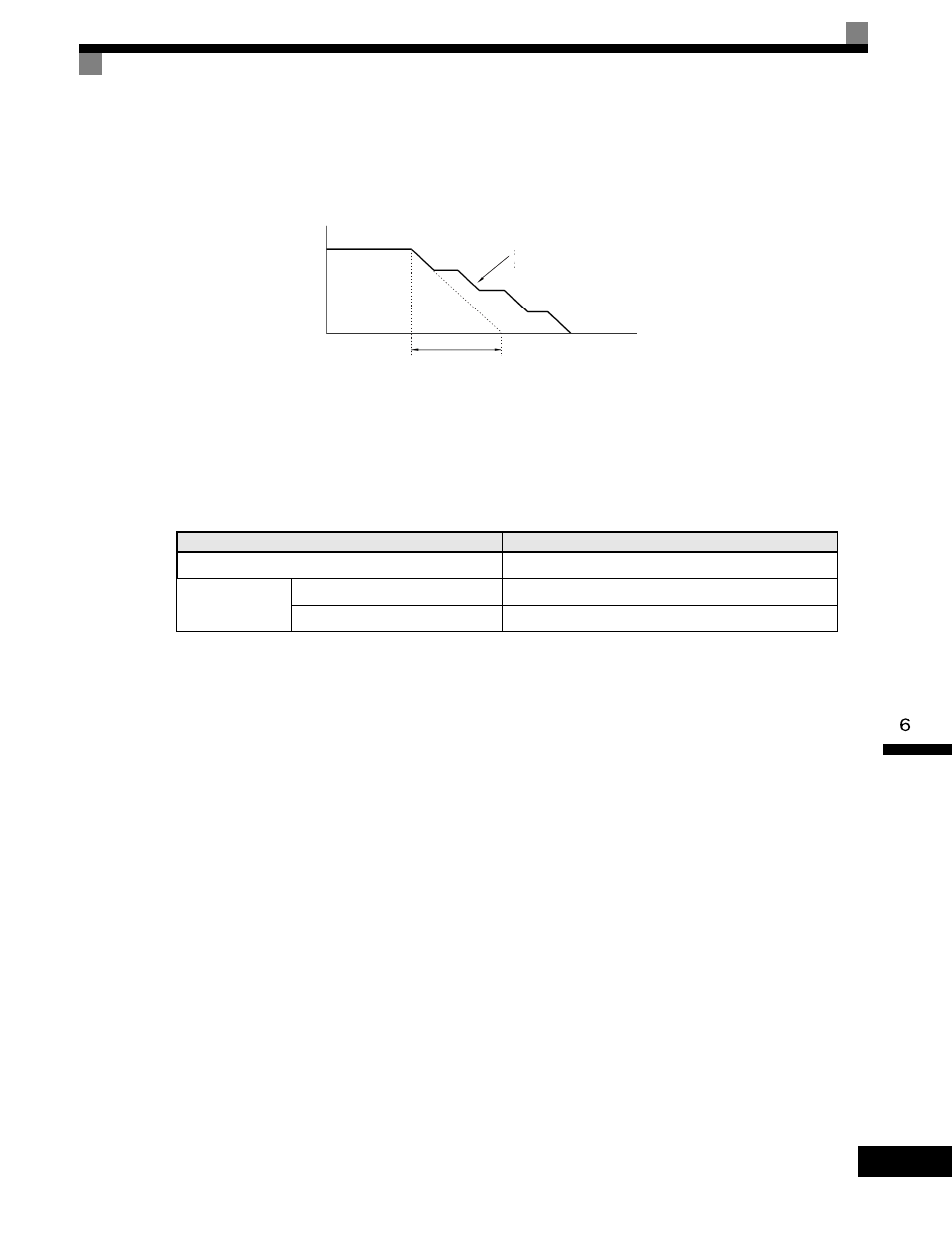
An example of stall prevention during deceleration when L3-04 is set to 1 as shown below.
Fig 6.23 Stall Prevention During Deceleration Operation
Setting Precautions
•
The stall prevention level during deceleration differs depending on the Drive capacity. Refer to the follow-
ing table for details.
•
When using the braking option (braking resistor, Braking Resistor Units, and Braking Units), be sure to set
parameter L3-04 to 0 or 3.
•
To decelerate at a shorter time than the deceleration time set when L3-04 is set to 0 with the braking option
enabled, set L3-04 to 3.
•
The setting of L3-04 is ignored for flux vector control or open-loop vector control 2.
Drive Capacity
Stall Prevention Level during Deceleration (V)
200-240Vclass
380
380-480Vclass
E1-01
≥ 400 V
760
E1-01 < 400 V
660
Deceleration time controlled to
prevent overvoltage
Deceleration time
(set value)
Time
Output frequency