Digital operator functions, Setting digital operator functions, Related parameters – Yaskawa G7 Drive User Manual
Page 356: Digital operator functions -139, Setting digital operator functions -139
Digital Operator Functions
6-
139
Digital Operator Functions
This section explains the Digital Operator functions.
Setting Digital Operator Functions
You can set Digital Operator-related parameters such as selecting the Digital Operator display, multi-function
selections, and copy functions.
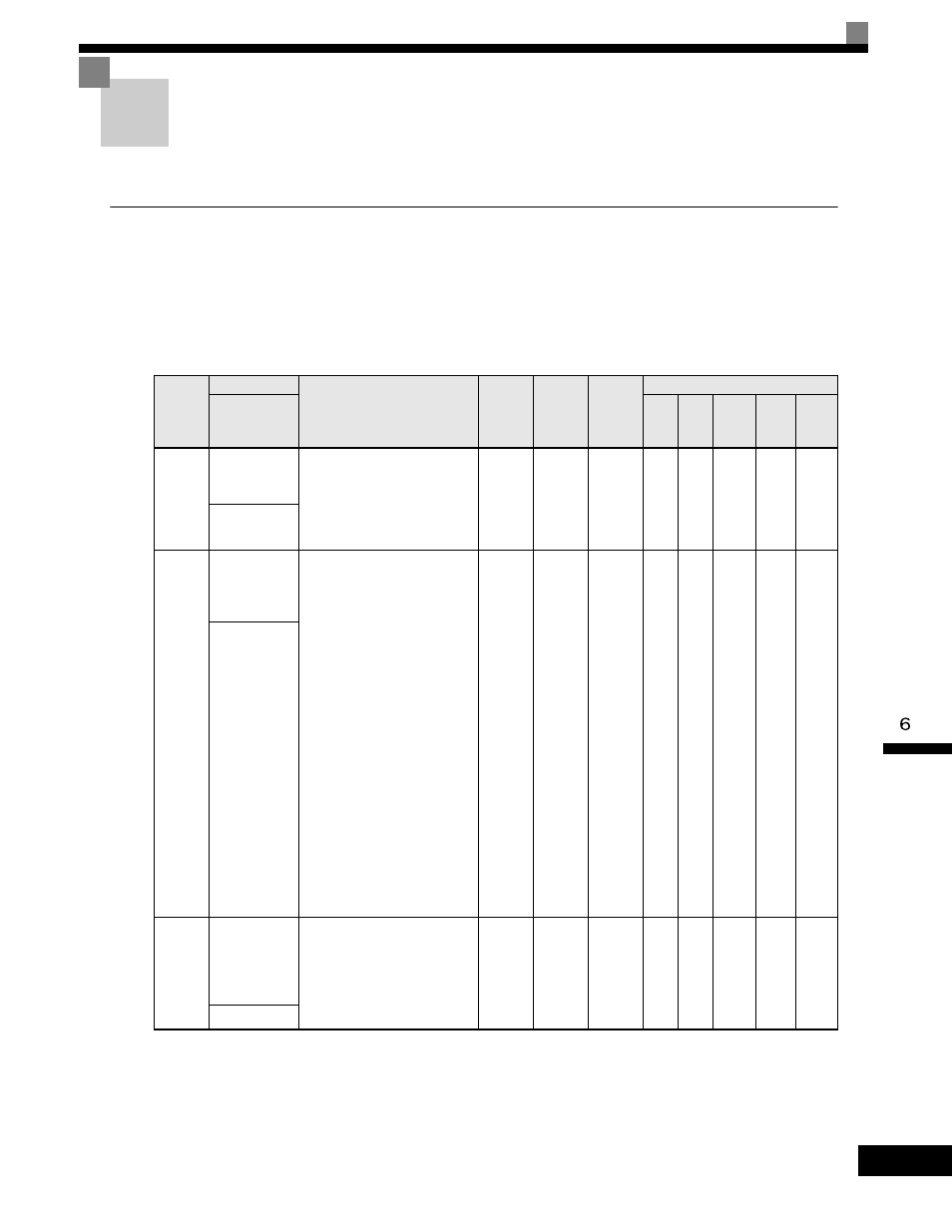
Related Parameters
Parameter
Number
Name
Description
Setting
Range
Factory
Setting
Change
during
Operation
Control Methods
Display
V/f
V/f
with
PG
Open
Loop
Vector
1
Flux
Vector
Open
Loop
Vector
2
o1-02
User Monitor
Selection After
Power-Up
Selects which monitor will be
displayed upon power-up.
1: Frequency Reference (U1-01)
2: Output Frequency (U1-02)
3: Output Current (U1-03)
4: User Monitor (set by o1-01)
1 to 4
1
Yes
A
A
A
A
A
Power-On
Monitor
o1-03
Digital
Operator
Display
Selection
Sets the units of the Frequency
References (d1-01 to d1-17), the
Frequency Reference Monitors
(U1-01, U1-02, U1-05), and the
Modbus communication
frequency reference.
0: Hz
1: % (100% = E1-04)
2 to 39: RPM (Enter the number
of motor poles).
40 to 39999: User display.
Set the number desired at
maximum output frequency.
4 digit number
Number of digits from the right of
the decimal point.
Example 1: o1-03 = 12000, will
result in frequency reference from
0.0 to 200.0 (200.0 = Fmax).
Example 2: o1-03 = 21234, will
result in frequency reference from
0.00 to 12.34 (12.34 = Fmax).
0
to
39999
0
No
A
A
A
A
A
Display Scaling
o1-04
Setting unit for
frequency
parameters
related to V/F
characteristics
Sets the setting units related to
V/F pattern frequency related
parameters (E1-04, -06, -09, -11)
0: Hertz
1: RPM
0 to 1
0
No
No
No
No
A
A
Display Units