Yaskawa G7 Drive User Manual
Page 201
5
-90
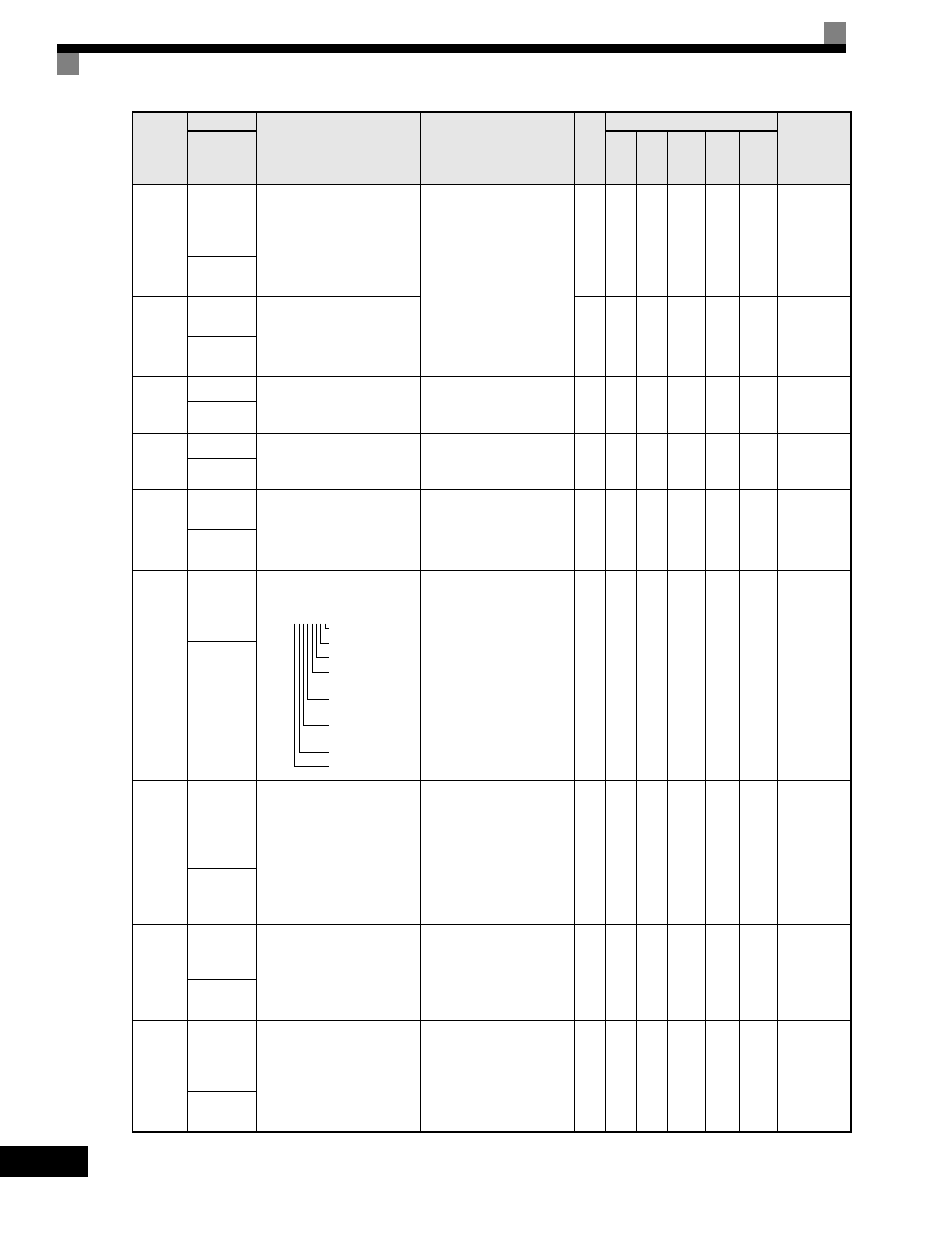
U1-34
First
Parameter
Causing an
OPE
Parameter number causing an
"OPE" fault.
No output possible.
-
A
A
A
A
A
61H
OPE
Detected
U1-35
Zero Servo
Pulse Count Number of PG pulses times 4
for the movement range when
stopped at zero servo.
1
No
No
No
A
No
62H
Zero Servo
Pulse
U1-36
PID Input
Input error to the PID
regulator (PID Setpoint - PID
Feedback).
10V: Maximum Frequency
(possible for -10V thru +10V)
0.0
1%
A
A
A
A
A
63H
PID Input
U1-37
PID Output Output of the PID regulator as
a percentage of maximum
frequency (E1-04).
10V: Maximum Frequency
(possible for -10V thru +10V)
0.0
1%
A
A
A
A
A
64H
PID Output
U1-38
PID
Setpoint
Setpoint of the PID regulator
(PID reference + PID bias).
10V: Maximum Frequency
0.0
1%
A
A
A
A
A
65H
PID
Setpoint
U1-39
Modbus
Communi-
cation Error
Code
Modbus serial communication
error codes.
No output possible.
-
A
A
A
A
A
66H
Transmit
Err
U1-40
Heatsink
Cooling
Fan
Operation
Time
Total operating time of the
heatsink cooling fan.
No output possible.
1
hr
A
A
A
A
A
68H
FAN
Elapsed
Time
U1-42
Motor Flux
Calculation
Values
Monitors the calculated motor
flux.
10V: Monitor rated flux.
0.1
%
No
No
No
No
A
69H
Mot Flux
EST
U1-43
Motor Flux
Current
Compensa-
tion
Shows 100% when the motor
rated secondary current
monitor for motor flux current
compensation is active.
10V: Motor Rated Secondary
Current
(0V to ±10V)
0.1
%
No
No
No
No
A
6AH
Id Comp
Value
Parameter
Number
Name
Description
Output Signal Level
During Multi-Function
Analog Output
Min.
Unit
Control Methods
MODBUS
Register
Display
V/f
V/f
with
PG
Open
Loop
Vector
1
Flux
Vector
Open
Loop
Vector
2
1: CRC error
1: Data length error
Not used (always 0).
1: Parity
error
1: Overrun
error
1: Framing
error
1: Timeout
Not used (always 0).
U1-40= 00000000