Trial operation procedure, Trial operation procedure -2 – Yaskawa G7 Drive User Manual
Page 91
4
-2
Trial Operation Procedure
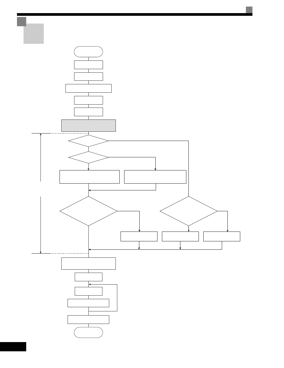
Perform trial operation according to the following flowchart.
Fig 4.1 Trial Operation Flowchart
V/f with PG
(A1-02 = 1)
START
Installation
Wiring
Turn ON power.
Confirm status.
Basic settings
(Quick programming mode)
Set power supply voltage.
Select operating
method.
Settings according
to control mode
Application settings
(Advanced programming mode)
No-load operation
Loaded operation
Optimum adjustments and
constant settings
Check/record constants.
END
YES
V/f
(Default: A1-02 = 0)
Vector (A1-02 = 2, 3, or 4)*5
Set E1-03.
V/f default: 200 V/60 Hz(400 V/60 Hz)
Set E1-03, E2-04, and F1-01.
V/f default: 200 V/60 Hz (400 V/60 Hz)
YES
NO
YES
NO
V/f control?
PG?
Motor cable over
50 m or heavy load possibly
causing motor to stall or
overload?
OK to operate
motor during autotuning?
Stationary autotuning for
line-to-line resistance only
Rotational autotuning
Stationary autotuning
*3
*4
*2
*1 Set for 400 V Class Inverter for 55 kW or more.
*2 If there is a reduction gear between the motor and PG, set
the reduction ratio in F1-12 and F1-13 in advanced
programming mode.
*3 Use rotational autotuning to increase autotuning accuracy
whenever it is okay for the motor to be operated.
*4 If the motor cable changes to 50 m or longer for the actual
installation, perform stationary autotuning for the line-to-line
resistance only on-site.
*5 The default control mode is open-loop vector control 2
(A1-02 = 2).
*1
*6
*6
*6 If the maximum output frequency and base frequency
are different, set the maximum output frequency (E1-
04) after autotuning.