Digital reference card: f3, Analog monitor cards: f4 – Yaskawa G7 Drive User Manual
Page 156
User Parameter Tables
5-
45
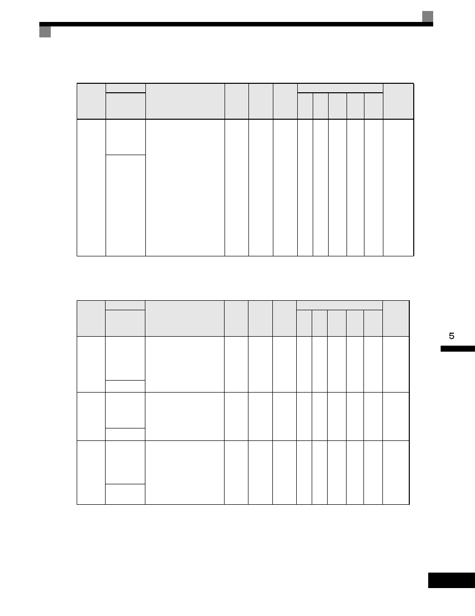
Digital Reference Card: F3
User parameters for the Digital Reference Card are shown in the following table.
Analog Monitor Cards: F4
User parameters for the Analog Monitor Card are shown in the following table.
Parameter
Number
Name
Description
Setting
Range
Factory
Setting
Change
during
Operation
Control Methods
MODBUS
Register
Display
V/f
V/f
with
PG
Open
Loop
Vector
1
Flux
Vector
Open
Loop
Vector
2
F3-01
DI-08 /
DI-16H2
Input
Selection
Sets the function of the DI-08
or the DI-16H2 digital input
option board.
0: BCD 1% unit
1: BCD 0.1% unit
2: BCD 0.01% unit
3: BCD 1Hz unit
4: BCD 0.1Hz unit
5: BCD 0.01Hz unit
6: BCD (5-digit) 0.01Hz unit
(only effective when
DI-16H2 is used.)
7: Binary input
When o1-03 is set to 2 or
higher, the input will be BCD,
and the units will change to
the o1-03 setting.
0 to 7
0
No
A
A
A
A
A
390H
DI Input
Parameter
Number
Name
Description
Setting
Range
Factory
Setting
Change
during
Operation
Control Methods
MODBUS
Register
Display
V/f
V/f
with
PG
Open
Loop
Vector
1
Flux
Vector
Open
Loop
Vector
2
F4-01
AO-08/
AO-12
Channel 1
Monitor
Selection
Sets the number of the
monitor item to be output.
(U1-oo). The following
settings cannot be used:
4, 10 to 14, 25, 28, 29, 30, 34,
35, 39, 40, 41.
1 to 45
2
No
A
A
A
A
A
391H
AO Ch1 Sel
F4-02
AO-08/
AO-12
Channel 1
Gain
Sets the channel 1 gain.
Ex: Set F4-02 = 50% to
output 100% at 5.0V
output.
0.0
to
1000.0
100%
Yes
A
A
A
A
A
392H
AO Ch1 Gain
F4-03
AO-08/
AO-12
Channel 2
Monitor
Selection
Sets the number of the
monitor item to be output.
(U1-xx). The following
settings cannot be set:
4, 10 to 14, 25, 28, 29, 30,
34, 39, 40, 41.
1 to 45
3
No
A
A
A
A
A
393H
AO Ch2
Select