Yaskawa G7 Drive User Manual
Page 58
Wiring Control Circuit Terminals
2-
27
The functions of DIP switch S1 are shown in the following table.
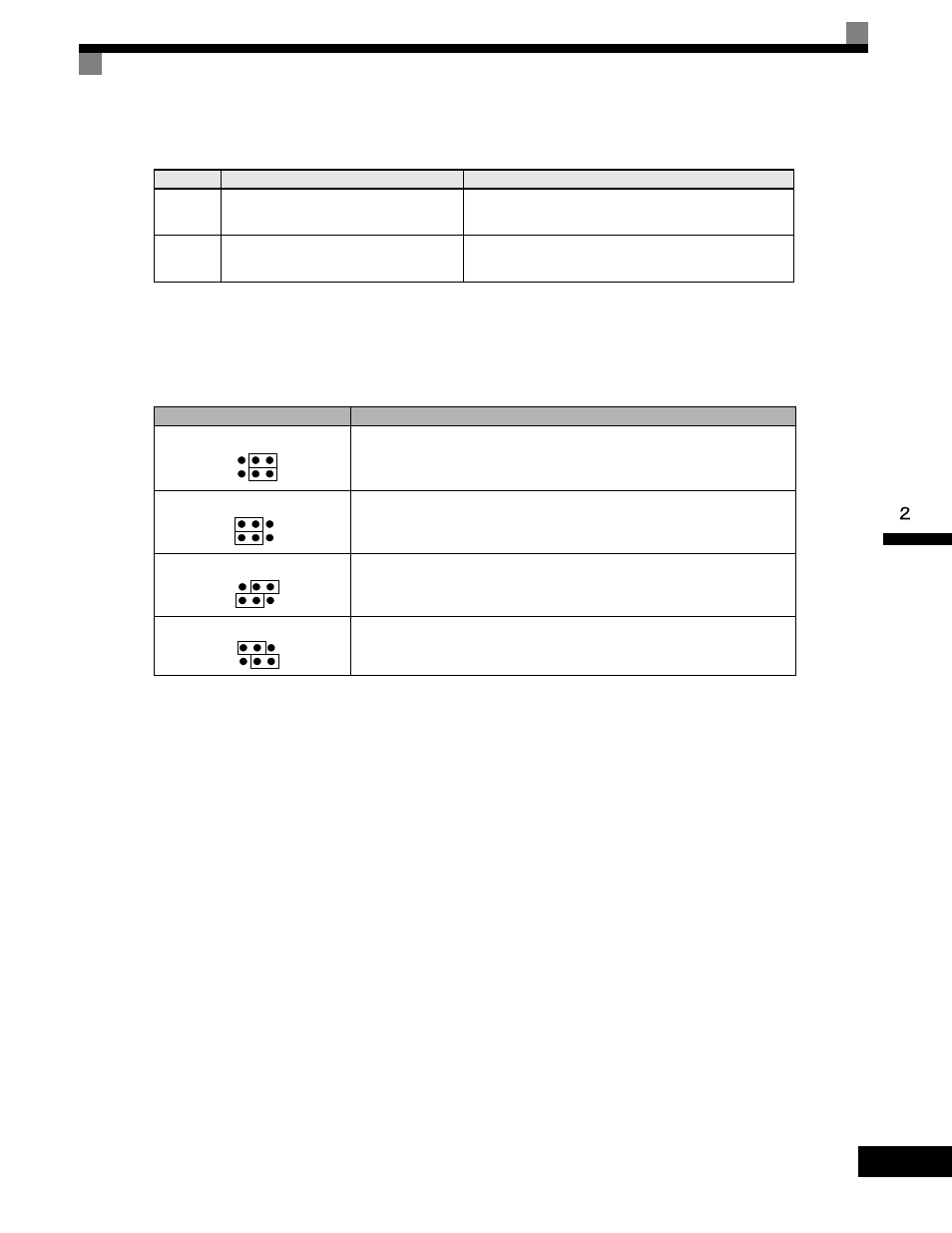
The functions and positions of CN15 are shown in the following table.
Table 2.11 DIP Switch S1
Name
Function
Setting
S1-1
RS-485 and RS-422 terminating resis-
tance
OFF: No terminating resistance
ON: Terminating resistance of 110
Ω
S1-2
Input method for analog input A2
OFF: 0 to 10 V (internal resistance: 20 k
Ω)
ON: 4 to 20 mA (internal resistance: 250
Ω)
Table 2.12 Jumper CN15 Configuration Options
Jumper CN15 Configuration
Analog Output Monitor Configuration
Voltage Output (0-10Vdc) for terminals FM-AC (CH1) and AM-AC (CH2)
Current Output (4-20mA) for terminals FM-AC (CH1) and AM-AC (CH2)
Voltage Output (0-10Vdc) for terminals FM-AC (CH1)
Current Output (4-20mA) for terminals AM-AC (CH2)
Current Output (4-20mA) for terminals FM-AC (CH1)
Voltage Output (0-10Vdc) for terminals AM-AC (CH2)