Setting precautions – Yaskawa G7 Drive User Manual
Page 243
6
-26
Adjusting Frequency Gain Using an Analog Input
When H3-09 or H3-05 is set to 1 (frequency gain), you can adjust the frequency gain using the analog input
terminal A2 or A3.
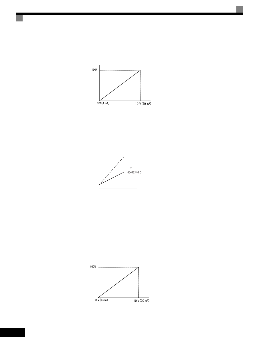
Fig 6.25 Frequency Gain Adjustment (Terminal A2 Input)
The frequency gain for terminal A1 is the sum of H3-02 and terminal A2 gain. For example, when H3-02 is set
to 100% and terminal A2 is set to 5 V, the terminal A1 frequency reference will be 50%.
Setting Precautions
H3-05 cannot be set to 0.
Adjusting Frequency Bias Using an Analog Input
When parameter H3-09 or H3-05 is set to 0 (add to terminal A1), the frequency equivalent to the terminal A2
or A3 input voltage is added to A1 as a bias.
Fig 6.26 Frequency Bias Adjustment (Terminal A2 or A3 Input)
Frequency gain
Multi-function analog input
terminal A2 input level
Frequency reference
H3-02
0
10 V
Terminal A1 input voltage
100%
50%
Frequency bias
Multi-function analog input
terminal A2 or A3 input level