Hardware protection: l8 – Yaskawa G7 Drive User Manual
Page 183
5
-72
Hardware Protection: L8
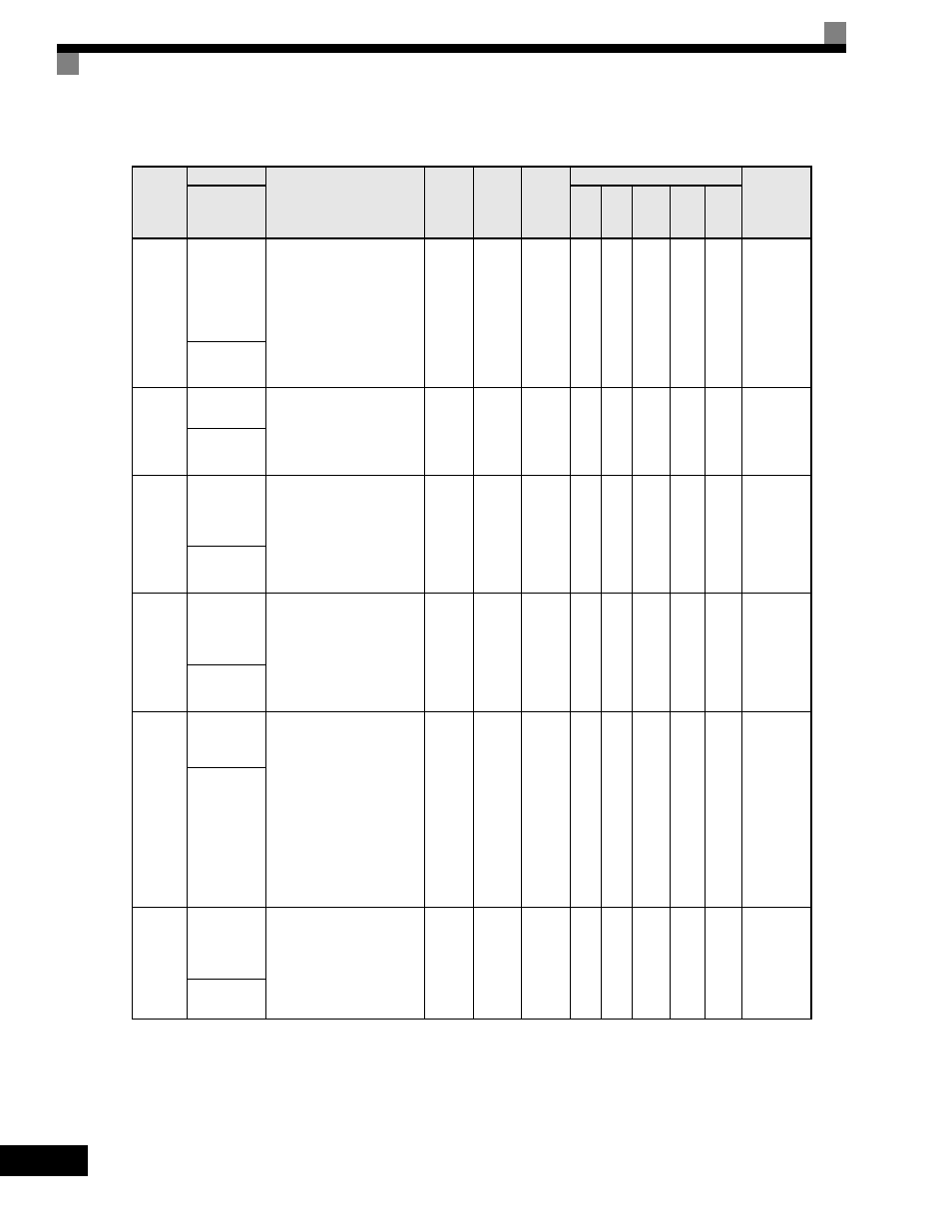
User parameters for hardware protection functions are shown in the following table.
Parameter
Number
Name
Description
Setting
Range
Factory
Setting
Change
during
Operation
Control Methods
MODBUS
Register
Display
V/f
V/f
with
PG
Open
Loop
Vector
1
Flux
Vector
Open
Loop
Vector
2
L8-01
Internal
Dynamic
Braking
Resistor
Protection
Selection
Selects the DB protection
only when using 3% duty
cycle heatsink mount
Yaskawa braking resistor.
This parameter does not
enable or disable the DB
function of the Drive.
0: Not Provided
1: Provided
0 to 1
0
No
A
A
A
A
A
4ADH
DB Resistor
Prot
L8-02
Overheat
Alarm Level
When the cooling fin
temperature exceeds the value
set in this parameter, an
Overheat Alarm (OH) will
occur.
50
to
130
95
°C*
No
A
A
A
A
A
4AEH
OH Pre-
Alarm Lvl
L8-03
Overheat
Pre-Alarm
Operation
Selection
Selects the Drive operation
upon an OH pre-alarm
detection.
0: Ramp to Stop
1: Coast to Stop
2: Fast-Stop
3: Alarm Only
0 to 3
3
No
A
A
A
A
A
4AFH
OH Pre-
Alarm Sel
L8-05
Input Phase
Loss
Protection
Selection
Selects the detection of input
current phase loss, power
supply voltage imbalance, or
main circuit electrostatic
capacitor deterioration.
0: Disabled
1: Enabled
0 to 1
0
No
A
A
A
A
A
4B1H
Ph Loss In
Sel
L8-07
Output Phase
Loss
Protection
Selects the detection method
for output phase loss.
When applied motor capacity
is too small for Drive
capacity, output phase loss
may be detected
inadvertently. In this case, set
to 0.
0: Disabled
1: Single Phase Loss
Detection
2: 2/3-phase Loss Detection
0 to 2
0
No
A
A
A
A
A
4B3H
Ph Loss Out
Sel
L8-09
Output
Ground Fault
Detection
Selection
Enables and disables the
Drive's output ground fault
detection.
0: Disabled
1: Enabled
0 to 1
1
No
A
A
A
A
A
4B5H
Ground Fault
Sel