Yaskawa G7 Drive User Manual
Page 41
2
-10
* The wire thickness is set for copper wires at 75
°C.
*
1
Wire size range provided for Drives using insulated screw-type terminal blocks with a single conductor. Refer to applicable codes for proper wire type and size.
*
2
Recommended wire sizes are based on the Drive current ratings and NEC Article 310 Table 310.16, 75 Degree Celsius copper or equivalent.
*
3
Uses non-insulated screw-type terminals. Refer to applicable codes for proper wire type and size.
G7U4160
R/L1, S/L2, T/L3,
,
1, U/T1, V/T2,
W/T3, R1/L11, S1/L21, T1/L31
M12
276 to 345
(31.4 to 39.2)
N/A
4/0
× 2P
(100
× 2P)
Power cables,
e.g., 600 V
vinyl power
cables
3
M8
78 to 95
(8.8 to 10.8)
Application
Dependent
M12
276 to 345
(31.4 to 39.2)
1/0
× 2P
(50
× 2P)
r/ 1, 200/
2
200, 400/
2
400
M4
11.4 to 12.3
(1.3 to 1.4)
16
(1.25)
G7U4185
R/L1, S/L2, T/L3, R1/L11, S1/L21, T1/
L31
M16
694 to 867
(78.4 to 98.0)
250 x 2P
(125 x 2P)
U/T1, V/T2, W/T3
250 x 2P
(125 x 2P)
, 1
600 x 2P
(325 x 2P)
3
Application
Dependent
3/0 x 2P
(80 x 2P)
r/ 1, 200/
2
200, 400/
2
400
M4
11.4 to 12.3
(1.3 to 1.4)
16
(1.25)
G7U4220
R/L1, S/L2, T/L3, R1/L11, S1/L21, T1/
L31
M16
694 to 867
(78.4 to 98.0)
350 x 2P
(185 x 2P)
U/T1, V/T2, W/T3
300 x 2P
(150 x 2P)
, 1
250 x 4P
(125 x 4P)
3
Application
Dependent
4/0 x 2P
(100 x 2P)
r/ 1, 200/
2
200, 400/
2
400
M4
11.4 to 12.3
(1.3 to 1.4)
16
(1.25)
G7U4300
R/L1, S/L2, T/L3, R1/L11, S1/L21, T1/
L31
M16
694 to 867
(78.4 to 98.0)
600 x 2P
(325 x 2P)
U/T1, V/T2, W/T3
500 x 2P
(300 x 2P)
, 1
400 x 4P
(200 x 4P)
3
Application
Dependent
250 x 2P
(125 x 2P)
r/ 1, 200/
2
200, 400/
2
400
M4
11.4 to 12.3
(1.3 to 1.4)
16
(1.25)
IMPORTANT
Determine the wire size for the main circuit so that line voltage drop is within 2% of the rated voltage. Line
voltage drop is calculated as follows:
Line voltage drop (V) =
x wire resistance (
Ω/km) x wire length (m) x current (A) x 10
-3
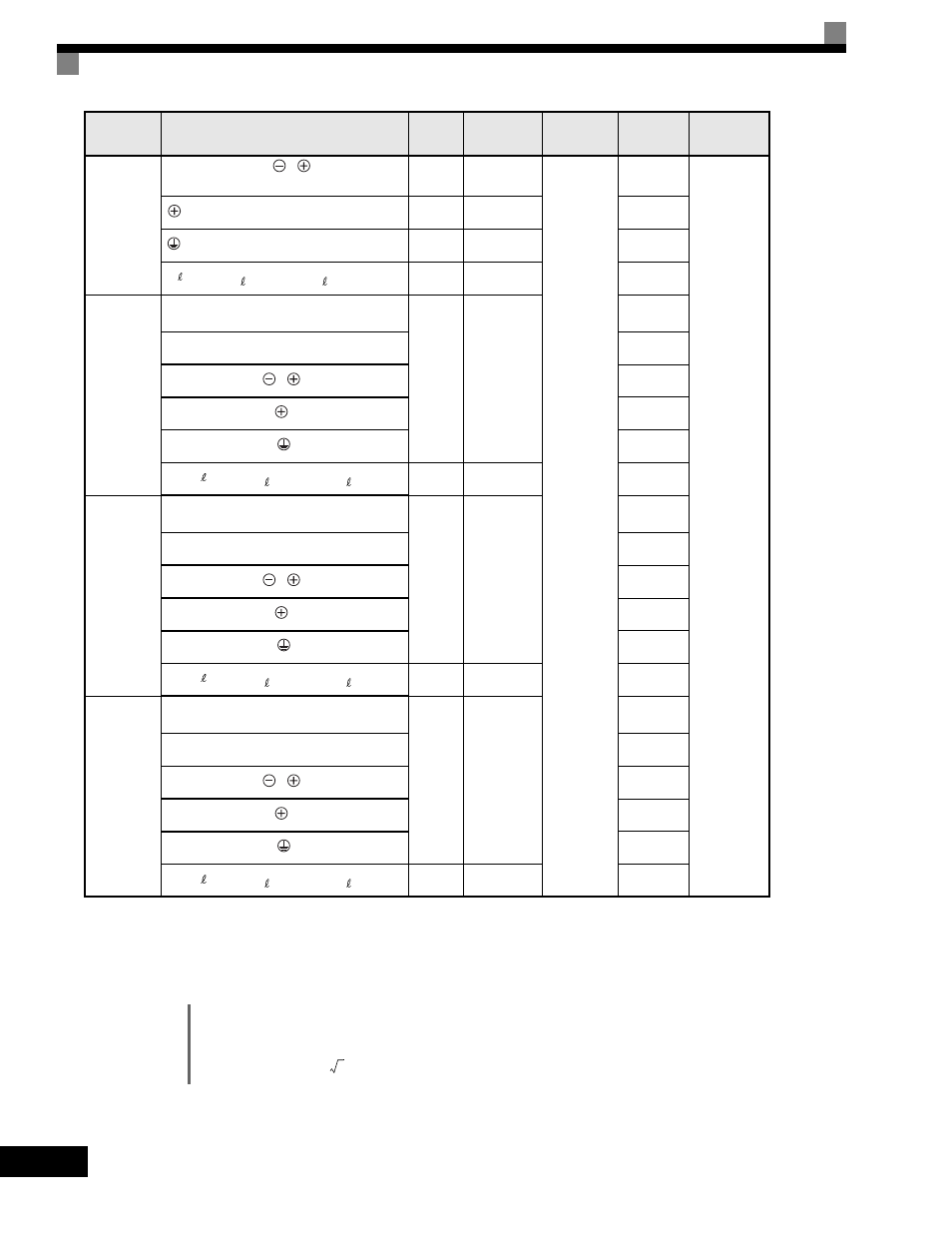
Drive Model
CIMR-
Terminal Symbol
Terminal
Screws
Tightening
Torque
(N•m)
Possible Wire
Sizes
mm
2
(AWG)
Recommended
Wire Size
mm
2
(AWG)
Wire Type
3