Frequency reference, Selecting the frequency reference source, Related parameters – Yaskawa G7 Drive User Manual
Page 219: Frequency reference -2, Selecting the frequency reference source -2
6
-2
Frequency Reference
This section explains how to input the frequency reference.
Selecting the Frequency Reference Source
Set parameter b1-01 to select the frequency reference source.
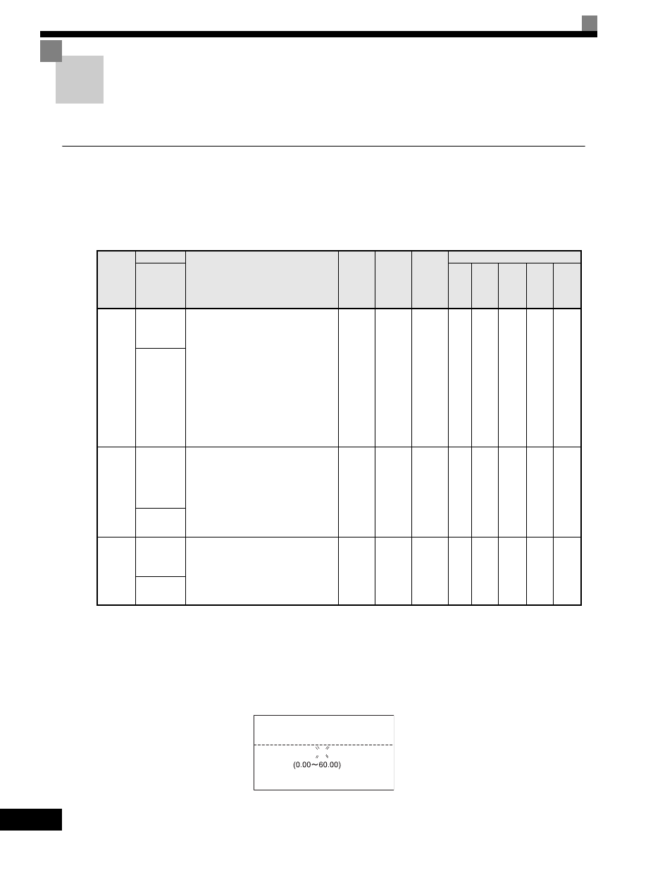
Related Parameters
Input the Reference Frequency from the Digital Operator
When b1-01 is set to 0, you can input the reference frequency from the Digital Operator.
Input the reference frequency from the Digital Operator's reference frequency setting display.
For details on setting the reference frequency, refer to Chapter 3 Digital Operator and Modes.
Fig 6.1 Frequency Setting Display
Parameter
Number
Name
Description
Setting
Range
Factory
Setting
Change
during
Operation
Control Methods
Display
V/f
V/f
with
PG
Open
loop
Vector
1
Flux
Vector
Open
Loop
Vector
2
b1-01
Frequency
Reference
Selection
Selects the frequency reference input
source.
0: Operator - Digital preset speed U1-01
or d1-01 to d1-17.
1: Terminals - Analog input terminal A1
(or terminal A2 based on parameter
H3-09).
2: Serial Com - Modbus RS-422/485
terminals R+, R-, S+, and S-.
3: Option PCB - Option board connected
on 2CN.
4: Pulse Input (Terminal RP)
0 to 4
1
No
Q
Q
Q
Q
Q
Reference
Source
H6-01
Terminal RP
Pulse Train
Input
Function
Selection
Selects the function of pulse train
terminal RP.
0: Frequency reference
1: PID feedback value
2: PID setpoint value
0 to 2
0
No
A
A
A
A
A
Pulse Input
Sel
H6-02
Pulse Train
Input
Scaling
Sets the number of pulses (in Hz) that is
equal to the maximum output frequency
E1-04.
1000 to
32000
1440Hz
Yes
A
A
A
A
A
Pulse In
Scaling
-DRIVE-
Frequency Ref
U1-01= 0 0 0.0 0Hz
-DRIVE-
Rdy
Frequency Ref
U1-01= 0 0 0.0 0Hz
"0.00Hz"