Data tables, Reference data – Yaskawa G7 Drive User Manual
Page 308
Individual Functions
6-
91
Data Tables
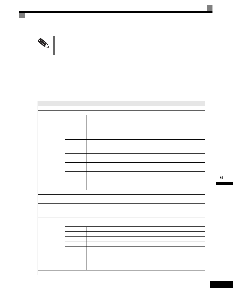
The data tables are shown below. The types of data are as follows: Reference data, monitor data, and broadcast
data.
Reference Data
The reference data table is shown below. You can both read and write reference data.
INFO
Set the number of data specified using command messages as quantity of specified messages x 2. Handle
response messages in the same way.
Register No.
Contents
0000H
Not used
0001H
Frequency reference
Bit 0
Run/stop command
1: Run 0: Stop
Bit 1
Forward/reverse operation
1: Reverse 0: Forward
Bit 2
External fault
1: Error (EFO)
Bit 3
Fault reset
1: Reset command
Bit 4
ComNet
Bit 5
ComCtrl
Bit 6
Multi-function input command 3
Bit 7
Multi-function input command 4
Bit 8
Multi-function input command 5
Bit 9
Multi-function input command 6
Bit A
Multi-function input command 7
Bit B
Multi-function input command 8
Bit C
Multi-function input command 9
Bit D
Multi-function input command 10
Bit E
Multi-function input command 11
Bit F
Multi-function input command 12
0002H
Frequency reference (Set units using parameter o1-03)
0003H
Not used
0004H
Torque reference
0005H
Torque compensation
0006H
PID target value
0007H
Analog output 1 setting (-11 V/-1540 to 10 V/1540)
0008H
Analog output 2 setting (-11 V/-1540 to 11 V/1540)
0009H
Multi-function contact output setting
Bit 0
Contact output (terminal M1-M2)
1: ON 0: OFF
Bit 1
Contact output (terminal M3-M4)
1: ON 0: OFF
Bit 2
Contact output (terminal M5-M6)
1: ON 0: OFF
Bit 3
PHC3(Contact P3-C3)
1: ON 0: OFF
Bit 4
PHC4(Contact P4-C4)
1: ON 0: OFF
Bit 5
Not used
Bit 6
Set error contact (terminal MA-MC) output using bit 7. 1: ON 0: OFF
Bit 7
Error contact (terminal MA-MC)
1: ON 0: OFF
Bits 8 to F
Not used
000AH to 000EH Not used